Net forming mechanism of gas flow type net forming machine

A web-forming machine and air-flow technology, which is applied in textiles and papermaking, fiber processing, fiber feeding, etc., can solve the problems of non-woven fiber technology enlightenment and cotton web, etc., and increase the speed of web forming , to avoid the effect of silting

Active Publication Date: 2012-06-20
JIANGSU YINGYANG NONWOVEN MASCH CO LTD
View PDF7 Cites 9 Cited by
  • Summary
  • Abstract
  • Description
  • Claims
  • Application Information

AI Technical Summary

Problems solved by technology

[0005]However, the above-mentioned patent solution is because the output curtain is arranged at the bottom of the cotton inlet passage, and the exhaust mechanism (the patent is called a wind pressure regulating box) is arranged at the bottom of the cotton inlet passage. Therefore, the following deficiencies are exposed in the actual web forming process: First, it is difficult to ensure that the thickness of the cotton web reaching the output curtain is fully consistent under the action of the exhaust mechanism on the side; It will hinder the rapid downward movement of the non-woven fibers in the cotton-feeding channel and affect the web-forming speed; third, because the exhaust mechanism is located on the side of the cotton-feeding channel, once

Method used


Image

  • Net forming mechanism of gas flow type net forming machine
  • Net forming mechanism of gas flow type net forming machine
  • Net forming mechanism of gas flow type net forming machine

Examples


Embodiment Construction

[0021] In order to enable the examiners of the patent office, especially the public, to understand the technical essence and beneficial effects of the present invention more clearly, the applicant will describe in detail the following in the form of examples, but none of the descriptions to the examples is an explanation of the solutions of the present invention. Any equivalent transformation made according to the concept of the present invention which is merely formal but not substantive shall be regarded as the scope of the technical solution of the present invention.

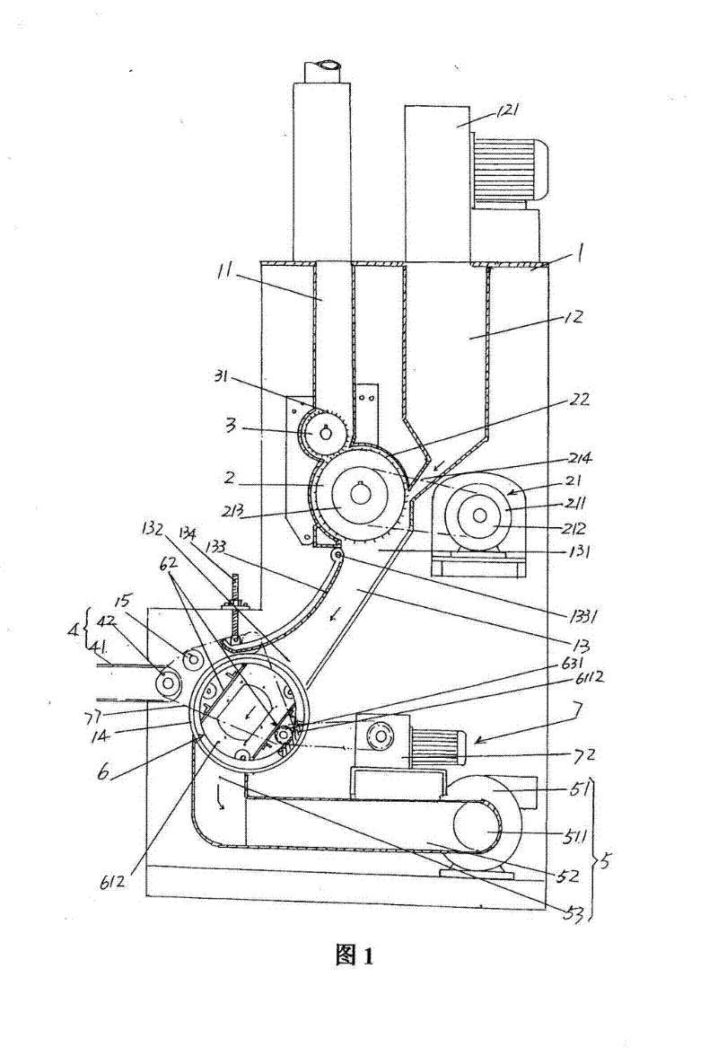
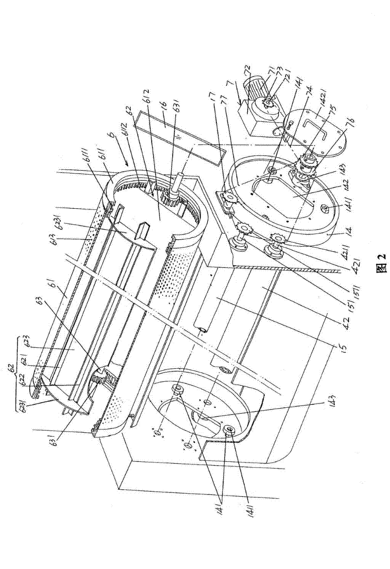
[0022] please see figure 1 and figure 2 , given a rack 1, given by figure 1 As shown, a cotton mixing box 11 is provided on the top of the frame 1, and the non-woven fiber cotton that is loosened by the opener of the previous process is introduced in the cotton mixing box 11. Again, an air inlet duct 12 is arranged on the top of the frame 1, by figure 1 The blower 121 is shown to introduce press...


PUM


Abstract

The invention relates to a net forming mechanism of a gas flow type net forming machine, belonging to the technical field of non-weaving machinery. The gas flow type net forming machine comprises a frame, large and small taker-in rollers, a cotton net output mechanism and an air draft mechanism, wherein the frame is provided with a cotton blending box, an inlet duct and a cotton inflow channel. The net forming mechanism comprises a dust cage device and a dust cage driving device, wherein the dust cage device comprises a dust cage drum body, a pair of air channel partition mechanisms and a gear shaft; air suction holes are distributed on the dust cage drum body, dust cage rings are fixed at two ends of the dust cage drum body, roller wheel grooves are opened on the inner walls of the dust cage rings so as to form gear rings, gears are fixed at two ends of the gear shaft, and the gears are meshed with the gear rings; and the dust cage driving device is arranged on the frame; the cotton net output mechanism corresponds to one side of the dust cage drum body; and the air draft mechanism corresponds to the bottom of the dust cage drum body. The net forming mechanism has the advantages that nonwoven fiber cotton is conveyed to the cotton net output mechanism at a uniform thickness; and the net forming speed is increased, the stagnation of the nonwoven fiber in the cotton inflow channel is avoided and the interference of the air draft mechanism on the cotton net output mechanism is not generated.

Description

technical field [0001] The invention belongs to the technical field of non-woven machinery, and in particular relates to a web forming mechanism of an airflow web forming machine. Background technique [0002] The air-flow web forming machine is also called the air-flow cotton feeder. Its function is to form a cotton web from the non-woven fibers after opening in the previous process, and transport it to the final shaping equipment to obtain non-woven products. Non-woven products such as Non-woven fabrics, non-woven felts, etc. [0003] The air-flow web forming mechanism plays an extremely important role in the production line of complete sets of non-woven products, because whether the thickness of the cotton web layer after web formation is uniform or not affects the shaping, and ultimately affects the consistency of the weight of non-woven products. Influence. [0004] In the published Chinese patent literature, there have been reports of air-laid web forming machines, t...

Claims


Application Information

Patent Timeline
IPC IPC(8): D01G23/00D01G23/08
Inventor 范立元
Owner JIANGSU YINGYANG NONWOVEN MASCH CO LTD
Why Eureka
Try Eureka