Refrigerating system with ejector and refrigerating method thereof

A refrigeration system and ejector technology, which is applied in refrigerators, refrigeration and liquefaction, lighting and heating equipment, etc., can solve problems such as troublesome cooling capacity of the refrigeration system, affecting the stability of the refrigeration system, and reducing the efficiency of the ejector, so as to increase the pressure, Avoid efficiency decline and reduce the effect of impact

Inactive Publication Date: 2012-06-20
SHANGHAI JIAO TONG UNIV
View PDF5 Cites 17 Cited by
  • Summary
  • Abstract
  • Description
  • Claims
  • Application Information

AI Technical Summary

Problems solved by technology

There are many similar patents on the application of ejectors in refrigeration systems. The main function of ejectors is to completely or partially replace the expansion valve, reduce throttling losses, and improve the efficiency of refrigeration systems. However, since the mainstream fluid at the inlet of the ejector is Liquid refrigerant, in the expansion process of the nozzle, there will be a metastable flow phenomenon, which will reduce the efficiency of the nozzle, and the refrigerant will easily generate shock waves during the mixing and diffusion process in the ejector, which will reduce the efficiency of the ejector. Now and there is no good way to solve this problem
Moreover, as the external working conditions change, the performance of the ejector will also be affected, thereby affecting the stability of the refrigeration system and causing great trouble to the control of the cooling capacity of the refrigeration system.

Method used


Image

  • Refrigerating system with ejector and refrigerating method thereof
  • Refrigerating system with ejector and refrigerating method thereof
  • Refrigerating system with ejector and refrigerating method thereof

Examples


Embodiment 1

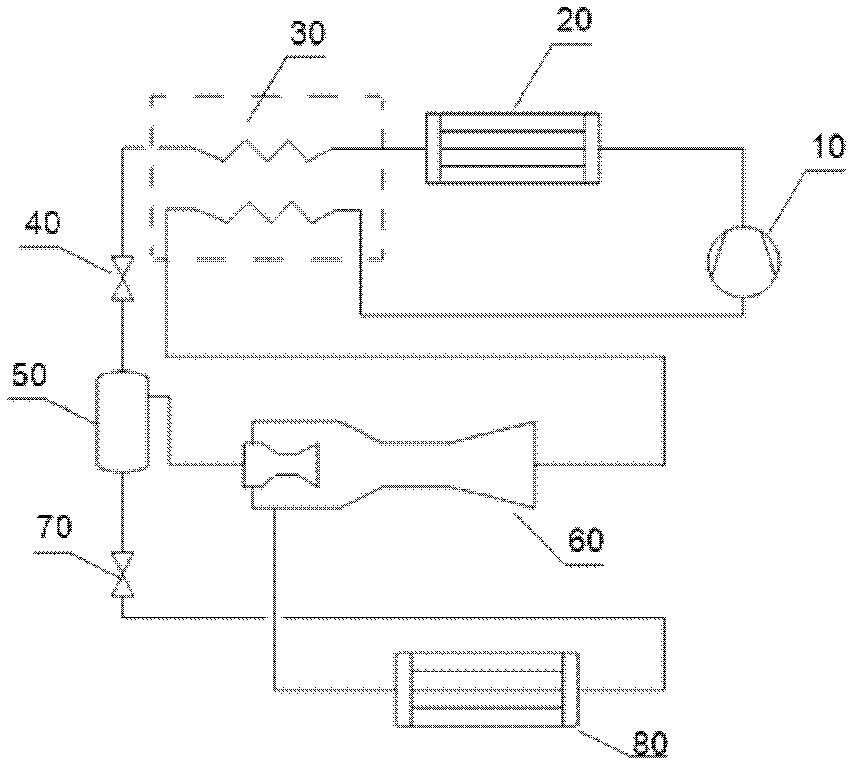
[0017] Such as figure 1 As shown, the refrigerating system with ejector of the present embodiment is composed of compressor 10, condenser 20, intermediate heat exchanger 30, expansion valve 40, gas-liquid separator 50, ejector 60, expansion valve 70 and evaporator 80 compositions. The connection relationship between the components: the outlet of the compressor 10 is connected to the inlet of the condenser 20, and then the outlet of the condenser 20 is connected to the inlet of the first side of the intermediate heat exchanger 30, and then the outlet of the first side of the intermediate heat exchanger 30 The outlet is connected with the inlet of the expansion valve 40, and then the outlet of the expansion valve 40 is connected with the inlet of the gas-liquid separator 50, and then the gas outlet of the gas-liquid separator 50 is connected with the main flow inlet of the injector 60, and the liquid of the gas-liquid separator 50 The outlet is connected to the inlet of the exp...

Embodiment 2

[0023] Such as Figure 4As shown, this embodiment includes: a refrigeration system with an ejector, which is composed of a compressor 10 , a condenser 20 , an expansion valve 40 , a gas-liquid separator 50 , an ejector 60 , an expansion valve 70 , and an evaporator 80 . The connection relationship of each component: the compressor 10 is connected to the condenser 20, then the condenser 20 is connected to the expansion valve 40, then the expansion valve 40 is connected to the gas-liquid separator 50, and then the gas outlet of the gas-liquid separator 50 is connected to the ejector 60 The main flow inlet is connected, and the liquid outlet of the gas-liquid separator 50 is connected with the expansion valve 70, and then the expansion valve 70 is connected with the evaporator 80, and then the evaporator 80 is connected with the ejector 60 gas injection inlet, and then the ejector 60 is connected with the compressor 10 connections to form a complete loop.

[0024] After being co...


PUM


Abstract

The invention discloses a refrigerating system with an ejector. The main trend of ejectors is that: a working medium becomes a gaseous working medium through an expansion valve, and the gaseous working medium from an evaporator enters the ejector for pressure expanding through injection, so that the pressure of the working medium is improved; and the working medium is compressed in a compressor and enters a condenser to finish a refrigerating cycle. However, according to the invention, a liquid working medium passing through the expansion valve is continuously throttled through another expansion valve to have a low-temperature low-pressure state, is evaporated in the evaporator, becomes a gaseous working medium through heat absorption to be ejected into the ejector, is pressurized in the ejector and enters the condenser to finish a refrigerating cycle. Therefore, the pressure of the working medium in the compressor is improved, a pressure ratio of the compressor is reduced, and the power consumption of the compressor is reduced, so that the efficiency of the refrigerating system is improved.

Description

technical field [0001] The invention relates to an evaporation compression refrigeration system, in particular to an evaporation compression refrigeration system comprising an ejector. The invention also relates to a refrigeration method using the refrigeration system. Background technique [0002] Most of the existing refrigeration systems are composed of four major components: compressor, condenser, expansion valve, and evaporator. After being compressed by the compressor, the gaseous refrigerant enters the condenser to condense into a high-pressure and high-temperature liquid, and then expands through the expansion valve. After that, it becomes a low-temperature and low-pressure two-phase fluid, and then enters the evaporator to evaporate, absorbs the heat of the fluid outside the evaporator to vaporize, and then enters the compressor to complete a cycle. During the cycle of the refrigerant, the refrigerant from the outlet of the condenser The process of the liquid state...

Claims


Application Information

Patent Timeline
Patent Type & Authority Applications(China)
IPC IPC(8): F25B9/08
Inventor 陈江平金鑫胡继超赵宇
Owner SHANGHAI JIAO TONG UNIV
Why Eureka
Try Eureka