Multi-measuring-point planeness evaluation method based on support vector classification
A technology of support vector classification and support vector machine, which is applied in the direction of measuring devices and instruments, can solve the problems of complex calculation, falling into local optimum, and difficult to guarantee the accuracy of evaluation, so as to improve calculation efficiency, improve accuracy and reduce calculation The effect of data volume
- Summary
- Abstract
- Description
- Claims
- Application Information
AI Technical Summary
Problems solved by technology
Method used
Image

Examples
Embodiment Construction
[0016] In order to make the purpose, technical solutions and advantages of the present invention clearer, the implementation of the present invention will be further described in detail below in conjunction with the accompanying drawings:
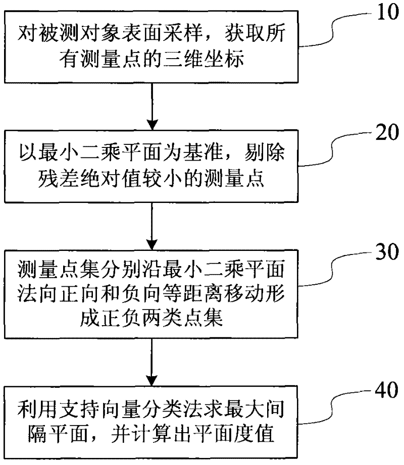
[0017] see figure 1 , is a multi-measuring point flatness evaluation method flow chart based on support vector classification, and the method includes the following steps:
[0018] Step 10 samples the points on the surface to be measured, and obtains the three-dimensional coordinates of all measurement points.
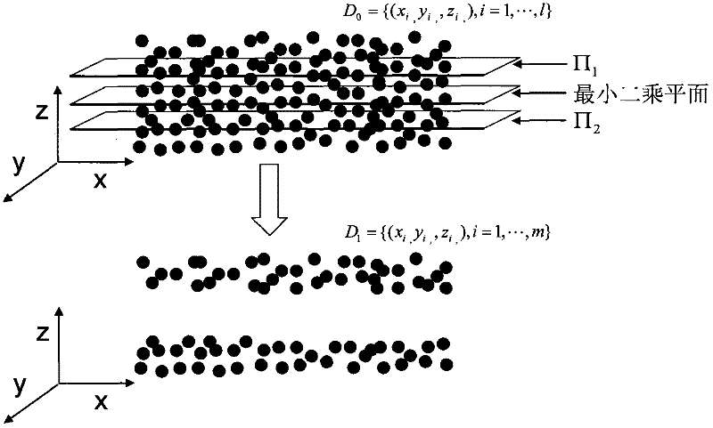
[0019] Step 20 calculates the least squares plane corresponding to the measurement point set, and based on the least squares plane, eliminates the measurement points with smaller residual absolute value.
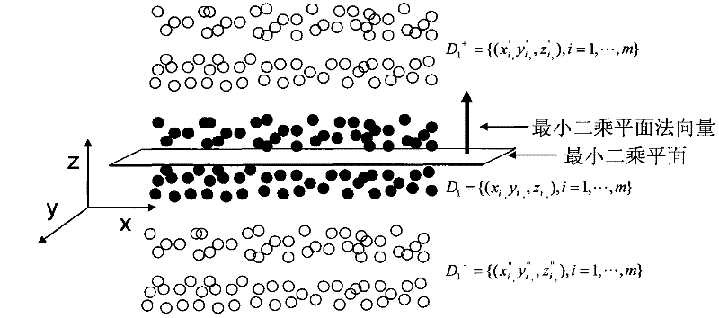
[0020] In step 30, the measurement points with large absolute values are moved equidistantly along the normal direction of the least squares plane in the positive and negative directions to form linearly separable positive and ...
PUM
 Abstract
Description
Claims
Application Information