Device and method for rapidly detecting time division multiplexing optical network link fault

A network link and optical multiplexing technology, which is applied in electromagnetic wave transmission systems, electrical components, transmission systems, etc., can solve the problems of low detection speed and large amount of calculation data, so as to improve the detection speed, solve the problem of large amount of calculation data, The effect of reducing the amount of calculated data

Active Publication Date: 2016-09-21
TAIYUAN UNIV OF TECH
View PDF5 Cites 6 Cited by
  • Summary
  • Abstract
  • Description
  • Claims
  • Application Information

AI Technical Summary

Problems solved by technology

[0004] In order to solve the problems of large amount of calculation data and low detection speed in existing time-division multiplexing passive optical network fault detection technology, the present invention provides a device and method for quickly detecting faults in time-division multiplexed optical network links

Method used


Image

  • Device and method for rapidly detecting time division multiplexing optical network link fault
  • Device and method for rapidly detecting time division multiplexing optical network link fault
  • Device and method for rapidly detecting time division multiplexing optical network link fault

Examples


Embodiment 1

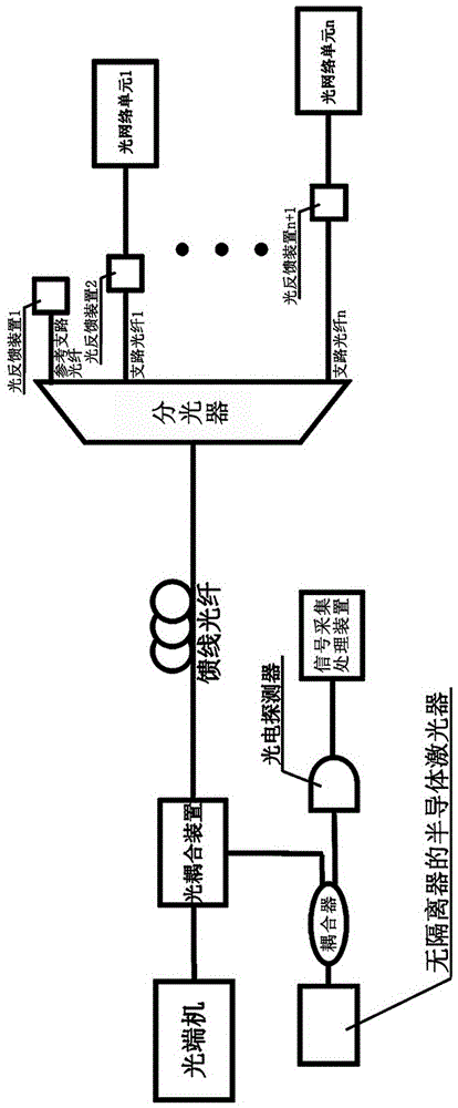
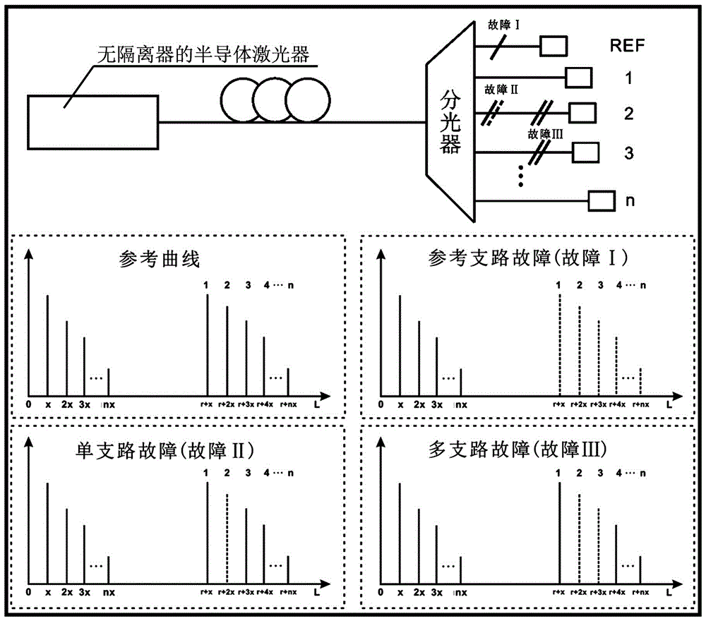
[0028] A device for quickly detecting link failures in a time-division multiplexing optical network, including a time-division multiplexing optical network and a detection device;

[0029] The time division multiplexing optical network includes an optical terminal, a feeder fiber, an optical splitter of 1 n+1 channels, n+1 optical fibers, and n optical network units; the shortest 1 optical fiber in the n+1 optical fibers is used as a reference branch The other n fibers are all used as branch fibers; the optical terminal is connected to the common port of the optical splitter through the feeder fiber; one of the n+1 split ports of the optical splitter connected to the reference branch fiber is defined as the first split port , and the remaining n splitter ports are respectively defined as the 2nd to n+1th splitter ports; the second to n+1th splitter ports of the optical splitter are connected to the incident end faces of n optical network units through n branch fibers in one-to-...

Embodiment 2

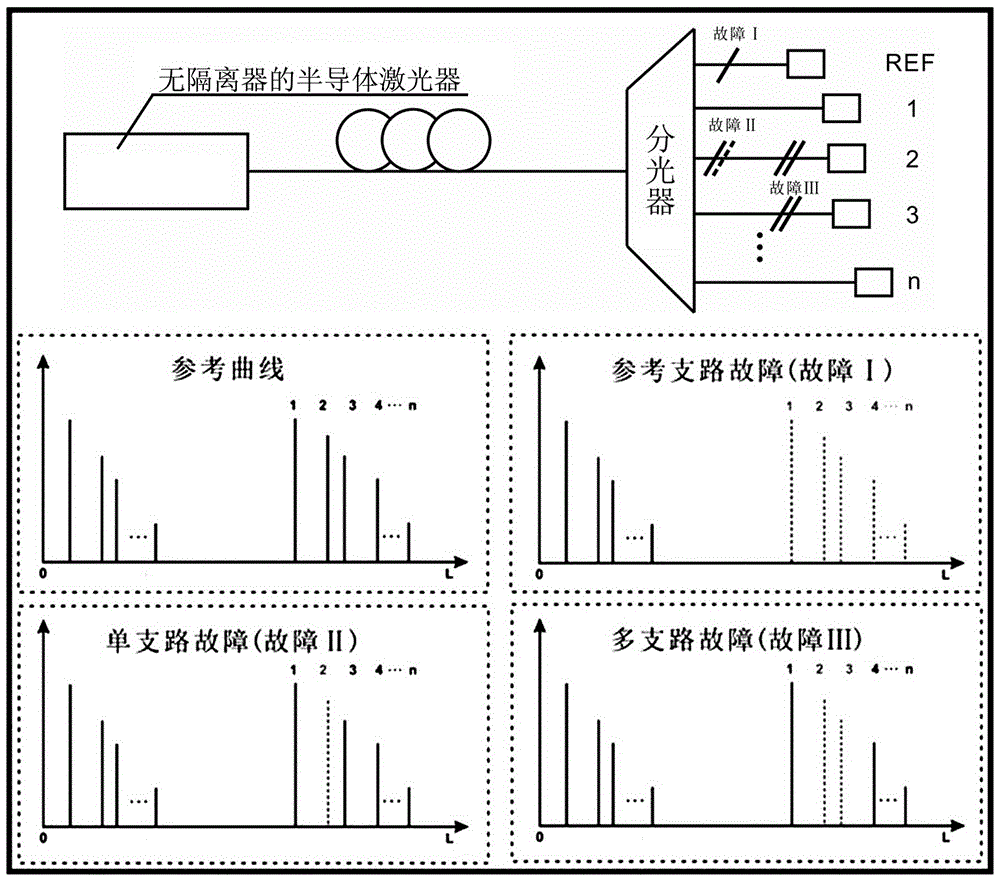
[0045] A device for quickly detecting link failures in a time-division multiplexing optical network, including a time-division multiplexing optical network and a detection device;

[0046] The time division multiplexing optical network includes an optical terminal, a feeder fiber, an optical splitter of 1 n+1 channels, n+1 optical fibers, and n optical network units; the shortest 1 optical fiber in the n+1 optical fibers is used as a reference branch The other n fibers are all used as branch fibers; the optical terminal is connected to the common port of the optical splitter through the feeder fiber; one of the n+1 split ports of the optical splitter connected to the reference branch fiber is defined as the first split port , and the remaining n splitter ports are respectively defined as the 2nd to n+1th splitter ports; the second to n+1th splitter ports of the optical splitter are connected to the incident end faces of n optical network units through n branch fibers in one-to-...


PUM


Abstract

The invention relates to the optical fiber communication network fault detection technology, and particularly relates to a device and method for rapidly detecting a time division multiplexing optical network link fault. The problems of a large calculation data amount and a low detection speed of existing time division multiplexing passive optical network fault detection technology are solved. The device comprises a time division multiplexing optical network and a detection device. The time division multiplexing optical network comprises an optical transmitter and receiver, a feedback optical fiber, 1 to (n+1) path light splitter, (n+1) fibers, and n optical network units. The detection device comprises a semiconductor laser without an isolator, a coupler, an optical coupling device, a photoelectric detector, a signal acquisition and processing device, and (n+1) optical feedback devices. The device and the method are suitable for the time division multiplexing passive optical network fault detection.

Description

technical field [0001] The invention relates to a fault detection technology of an optical fiber communication network, in particular to a device and method for quickly detecting faults in a time-division multiplexing optical network link. Background technique [0002] The communication rate of Time Division Multiplexed Passive Optical Network (TDM-PON, Time Division Multiplexed Passive Optical Network) has reached 100Gbps. For high-speed communication, once the communication is interrupted, the lost information will be difficult to count. If network faults can be detected and located one second earlier, the loss of hundreds of Gbits of information can be avoided. Therefore, fault detection in time-division multiplexing passive optical networks is particularly important. [0003] Currently, a commonly used fault detection method for time-division multiplexing passive optical networks is to use an Optical Time-Domain Reflectometry (OTDR, Optical Time-Domain Reflectometry) t...

Claims


Application Information

Patent Timeline
Patent Type & Authority Applications(China)
IPC IPC(8): H04B10/071
CPCH04B10/071
Inventor 韩红王大铭赵彤王安帮王云才王冰洁
Owner TAIYUAN UNIV OF TECH
Why Eureka
Try Eureka