
Probe card lifting mechanism

A lifting mechanism and probe card technology, used in measuring devices, instruments, measuring electrical variables, etc., can solve the problems of difficult to control the lifting speed, unstable lifting action, large vibration, etc., and achieve light, smooth, fast and stable lifting action. Effect

Active Publication Date: 2014-02-26
SUZHOU DONGKE ELECTRONICS
View PDF5 Cites 0 Cited by
  • Summary
  • Abstract
  • Description
  • Claims
  • Application Information

AI Technical Summary

Problems solved by technology

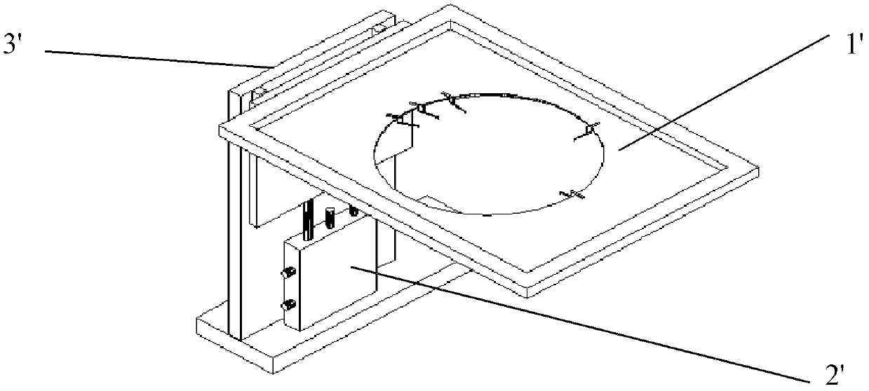
However, this method of adjusting the lifting of the probe card 1' through the lifting cylinder 2' is noisy, the lifting action is not stable, the vibration is large, and the lifting speed is difficult to control
When the vibration of the lifting action is large, it is easy to affect the accurate positioning of the working platform and the life of the probe
This kind of laser resistance adjustment machine probe card lifting mechanism, if the lifting action is fast, the vibration is relatively large; otherwise, the vibration is small, the lifting action is slow, and the laser resistance adjustment machine probe card lifting mechanism must be externally connected to a compressed air source

Method used


Image

  • Probe card lifting mechanism
  • Probe card lifting mechanism
  • Probe card lifting mechanism

Examples


Embodiment Construction

[0028] The technical solutions in the embodiments of the present invention will be described in detail below in conjunction with the accompanying drawings in the embodiments of the present invention. Obviously, the described embodiments are only some of the embodiments of the present invention, not all of them. Based on the embodiments of the present invention, all other embodiments obtained by persons of ordinary skill in the art without making creative efforts belong to the protection scope of the present invention.

[0029] see figure 1 As shown, a probe card lifting mechanism in the prior art includes a probe card 1', a lifting cylinder 2', an electromagnetic valve for adjusting the lifting of the cylinder, and a guide rail and slider group 3'. The probe card lifting mechanism uses the lifting cylinder 2' to achieve the lifting adjustment of the probe card 1'. Specifically, the lifting cylinder 2' moves back and forth by switching the electromagnetic valve, and the lifting...


PUM


Abstract

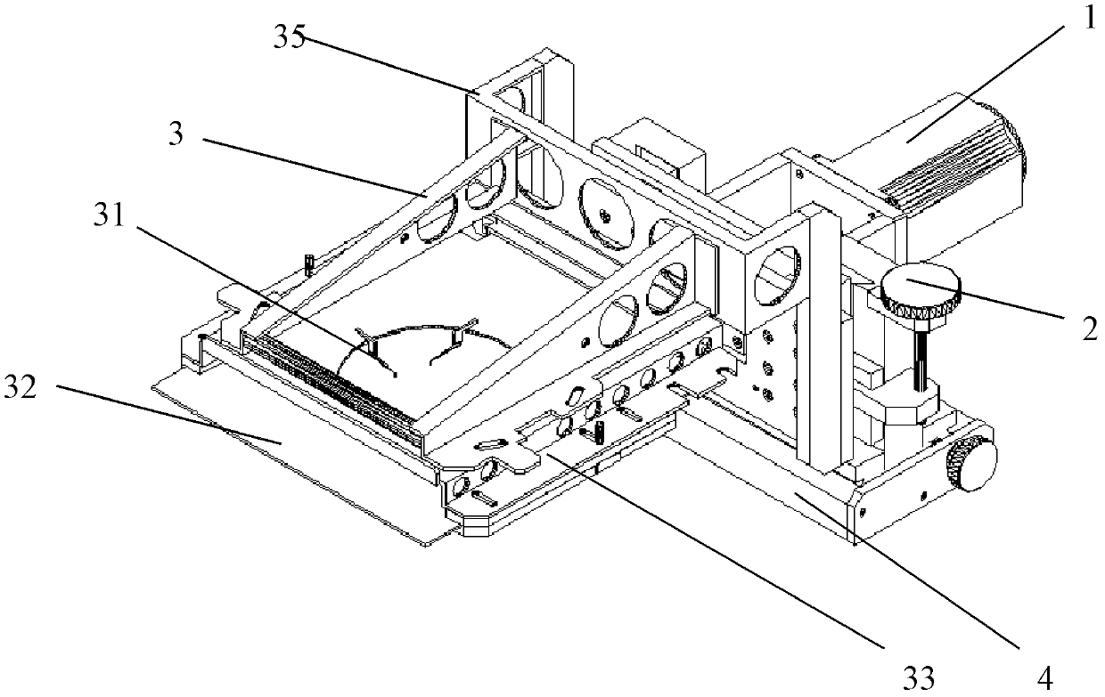
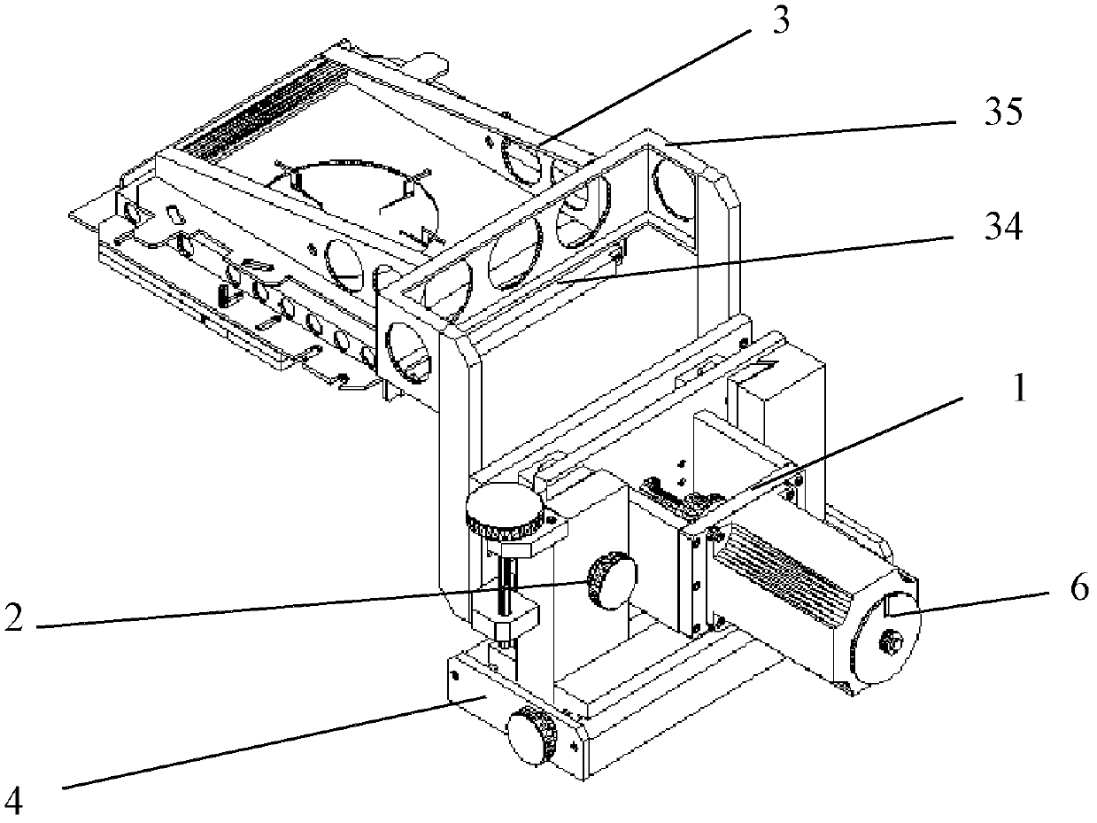
The invention discloses a probe card lifting mechanism. The probe card lifting mechanism comprises an electric lifting mechanism, a manual adjustment mechanism, a probe card mounting structure and a base, wherein the probe card mounting structure comprises a plurality of probes, a probe card, a mounting frame connecting piece and a probe card mounting frame, wherein the probe card is welded with the probes; the mounting frame connecting piece is connected with the electric lifting mechanism; the probe card mounting frame is used for connecting the probe cards and the mounting frame connecting piece; the electric lifting mechanism comprises a stepping motor, an eccentric wheel component and a lifting plate component; the eccentric wheel component is connected with the stepping motor; the probe card is connected with the lifting plate component through the mounting frame connecting piece; the eccentric wheel component converts the rotating action of the stepping motor into the lifting action of the lifting plate component; and the lifting plate component lifts to drive the probe card to ascend and descend. The lifting action of the probe card is finished by the stepping motor and the eccentric wheel component, so that the lifting action is light, smooth, quick and stable without vibration and noise, and lifting speed software can be adjusted.

Description

technical field [0001] The invention relates to a probe card lifting mechanism, in particular to a probe card lifting mechanism of a laser resistance trimming machine. Background technique [0002] During the laser trimming process, the measurement connection of the measurement circuit to each resistance is performed through a probe. The so-called probe is the measuring needle used by the measuring circuit to measure the resistance. Wherein, one end of the probe is in contact with the metal ends at both ends of the resistance (or the metal pad connected to the resistance), and the other end is connected with the measuring end of the relay matrix unit through the card holder and the cable. The probe card is a PCB board used for soldering probes. [0003] When the general laser resistance trimming machine enters, steps into or exits the laser resistance trimming area, the probe card must be lifted up to prevent the probe from being damaged or the probe touching the resistanc...

Claims


Application Information

Patent Timeline
Patent Type & Authority Patents(China)
IPC IPC(8): G01R15/00G01R27/02
Inventor 沈玉良
Owner SUZHOU DONGKE ELECTRONICS
Learn More