Image edge fusion projection method

An edge fusion and image projection technology, applied in the field of projection technology, can solve problems such as improvement, and achieve the effect of achieving overall brightness balance and seamless splicing.

Inactive Publication Date: 2012-06-20
王悦 +1
View PDF7 Cites 22 Cited by
  • Summary
  • Abstract
  • Description
  • Claims
  • Application Information

AI Technical Summary

Problems solved by technology

However, due to the limitations of projection technology, the brightness of each projected image decreases from the center to the edge. In the overlapping part of the projected images, due to double or even multiple projections, the brightness at the joints of different projection sources will increase significantly. projection effect

Method used


Image

  • Image edge fusion projection method
  • Image edge fusion projection method
  • Image edge fusion projection method

Examples


Embodiment 1

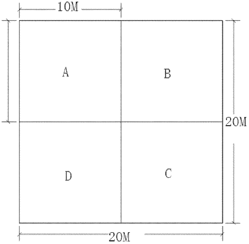
[0027] Take projecting a 400 (20x20) square meter as an example, and the output end is 4 projectors as an example.

[0028] according to figure 1 As shown, 4 projectors are used to project a target area of ​​400 square meters, and the steps are as follows:

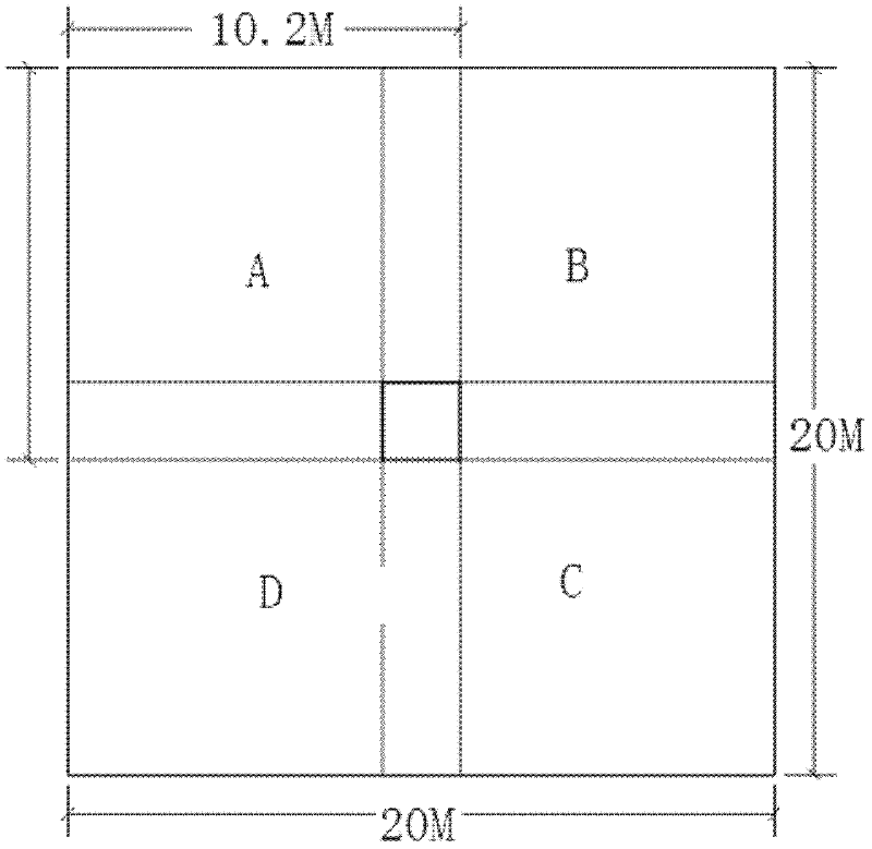
[0029] (1) The image divider divides the image into several regular graphics, which are respectively projected by different image projection devices; divides the target area into four equal parts of ABCD, that is, each part is 100 (10x10) square meters. In order to achieve the best fusion effect, in this example we use 2% overlap, and the edges of adjacent graphics overlap each other and graphics appear on the edges of adjacent graphics after segmentation; the actual area of ​​each projected image is 104.04 (10.2 x10.2) square meters, Figure 2 is a schematic diagram of its projected area.

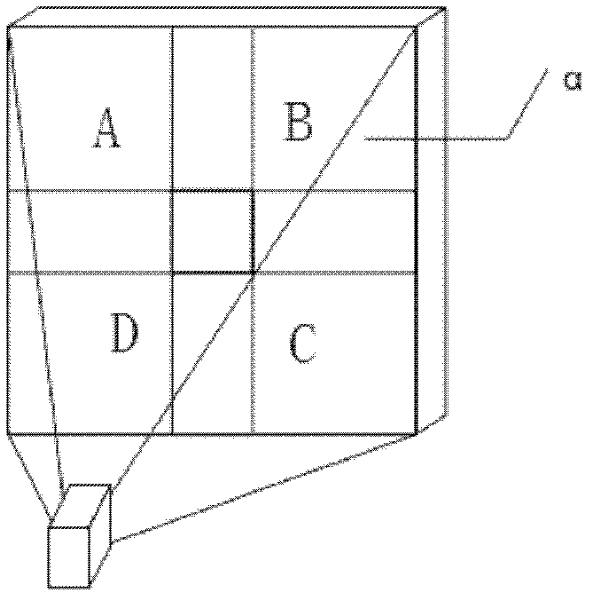
[0030] (2) Arrange criss-cross warps and latitudes on the entire image by the latitude and longitude routing instrument, and the col...


PUM


Abstract

The invention discloses a projection technology, particularly an edge fusion technology for displaying multiple unit projections on a large screen. An Image edge fusion projection method comprises the following steps of: processing and partitioning an original image picture; generating a corresponding independent video signal, and outputting to a preset projector matrix for projection, wherein adjacent projection images have overlapped parts; adjusting the brightness of the overlapped parts; and projecting according to adjusted parameters. The method has the advantage that: edges of a plurality of projection sources can be fused through a soft fusion method without adding a physical shading sheet. By adoption of an overlapped projection mechanism, seamless splicing and whole brightness balance are realized. The method can be widely applied to large-screen projection occasions.

Description

technical field [0001] The invention relates to a projection technology, in particular to an edge fusion technology for large screen and multi-unit projection splicing display. technical background [0002] Existing large-frame projection methods are usually realized by the following two methods: the first is to use a single high-power projector to project a complete image on a large screen, but this method generally requires a huge Throw distance and space requirements. In addition, due to the limited resolution of the projection device, when the image is enlarged, there will be obvious jaggedness at the edge of the image, which will reduce the image precision and affect the final projection effect. The second is the optical splicing method, that is, using multiple projectors to project optical images on a single large screen, and each projected image is connected with each other to form a complete, high-resolution projected image. However, due to the limitations of proje...

Claims


Application Information

Patent Timeline
Patent Type & Authority Applications(China)
IPC IPC(8): G03B21/00H04N5/74G06F3/14
Inventor 王悦卢彬
Owner 王悦
Why Eureka
Try Eureka