Conducting liquid contact-type friction-free rotary potentiometer

A conductive liquid, contact technology, applied in the direction of liquid resistors, etc., can solve the problems of non-sealing, mechanical friction of metal moving contacts, etc.

Inactive Publication Date: 2012-06-20
程有信
View PDF4 Cites 8 Cited by
  • Summary
  • Abstract
  • Description
  • Claims
  • Application Information

AI Technical Summary

Problems solved by technology

[0003] In order to overcome the technical problems of mechanical friction and non-sealing of the existing metal moving contacts of potentiometers,

Method used


Image

  • Conducting liquid contact-type friction-free rotary potentiometer

Examples


Embodiment Construction

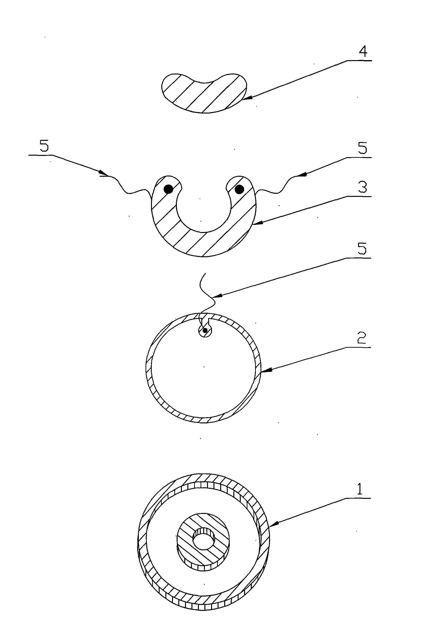
[0007] The conductive liquid contact type frictionless rotary potentiometer is processed like this. The material is made of 1mm plexiglass plate, and two rings with an outer radius of R1 and an inner radius of R4 are processed by a cutting lathe, marking A and B. The material is made of 3mm plexiglass plate, and a circle with an outer radius of R1 and an inner radius of R2 is processed by a cutting lathe, and the symbol C is used. A circle whose outer radius is R3 and whose inner radius is R4 marks D piece. The relationship between radius and length: where R1》R2》R3》R4. Assembly process: take piece A and lay it flat, take pieces C and D, and after one side is coated with glue, stick the concentric circles on the piece A. After sticking firmly, an annular groove is formed between R2 and R3 of C and D on A and D. The thickness (3mm) of the C piece and the D piece shall ensure that the depth of the annular groove is sufficient to install the circular arc-shaped exposed fixed re...


PUM


Abstract

The invention relates to an adjustable resistance device, in particular to a conducting liquid contact-type friction-free rotary potentiometer. The potentiometer provided by the invention adopts the structure that a ring-shaped conductive electrode (2), a circular arc-shaped naked fixed resistor (3), a conducting liquid drop (4), inert gas and external metallic sealing lead wires (5) are arranged in a ring-shaped gas-tight sealed box (1) in a built-in manner, wherein, two ends of the fixed resistor and the ring-shaped conductive electrode are both led out of the ring-shaped gas-tight sealed box (1) through the external metallic sealing lead wires (5). The rotary potentiometer provided by the invention has the benefits of mechanical contact prevention, friction and noise prevention, long service life, wide application, and the like; and due to the gravity action of the gravitational attraction, the potentiometer can be vertically mounted to be served as tilt sensors, shock sensors, displacement sensors, liquid level sensors, and the like.

Description

technical field [0001] The invention relates to an adjustable resistance device, in particular to a conductive liquid contact type frictionless rotary potentiometer. Background technique [0002] At present, the structure of the known potentiometer: the resistor body of the potentiometer is exposed and has two fixed ends. On the exposed resistor body, one or two movable metal moving contacts are tightly pressed, and the electrical contact is realized by mechanical friction between the metal moving contact and the exposed resistor body, and the metal moving contact is fixed to the rotating shaft or the sliding handle. The position of the movable contact determines the resistance value between the endpoint of either end of the resistor body and the contact. When in use, by manually adjusting the rotating shaft or sliding handle to change the position of the movable contact on the resistor body, the resistance value between the movable contact and any fixed end is changed, the...

Claims


Application Information

Patent Timeline
IPC IPC(8): H01C10/02
Inventor 程有信
Owner 程有信
Why Eureka
Try Eureka