Steel bar bender for building construction

A technology for steel bar bending and building construction, applied in the field of steel bar bending machines for building construction, can solve the problems of poor structural stability, inconvenient carrying, complex structure, etc., and achieve the effects of easy installation and disassembly, firm and reliable installation, and stable and reliable structure.

Inactive Publication Date: 2016-07-27
王春明
View PDF5 Cites 1 Cited by
  • Summary
  • Abstract
  • Description
  • Claims
  • Application Information

AI Technical Summary

Problems solved by technology

[0004] At present, the existing steel bar bending machine has a complex structure, is inconvenient to carry, has a large noise when used, and has poor structural stability.

Method used


Image

  • Steel bar bender for building construction

Examples


Embodiment Construction

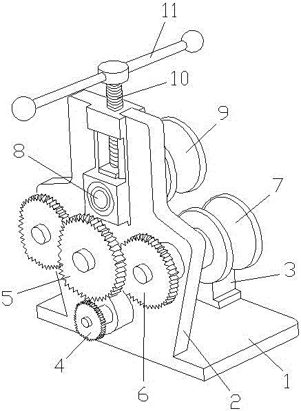
[0014] Such as figure 1 As shown, a steel bar bending machine for building construction includes a base 1, a locking sleeve 2, a hydraulic cylinder 3 and a piston rod 4. The locking sleeve 2 is arranged on the base 1, and the locking sleeve 2 and the base 1 Welding, the hydraulic cylinder 3 is set in the locking sleeve 2, the hydraulic cylinder 3 is clamped and connected with the locking sleeve 2, the locking sleeve 3 is provided with a fixing screw 5, and the piston rod 4 is set in the hydraulic pressure In the cylinder 3, the front end of the piston rod 4 is provided with a slider 6, the front end of the slider 6 is arranged in an arc shape, the two ends of the base 1 are equipped with rollers 7, and the middle part of the roller 7 is provided with a rotating shaft 8. The rotating shaft is welded to the base 1 , and the hydraulic cylinder 3 is provided with a hydraulic interface 9 and a handle 10 .

[0015] The hydraulic interface 9 is provided with two, which is convenient...


PUM


Abstract

The invention discloses a steel bar bender for building construction. The steel bar bender comprises a base, a lock sleeve, a hydraulic cylinder and a piston rod. The base is sleeved with the lock sleeve, and the lock sleeve and the base are welded. The hydraulic cylinder is arranged in the lock sleeve, and the hydraulic cylinder and the lock sleeve are in clamping connection. The lock sleeve is provided with fastening screws, the piston rod is arranged in the hydraulic cylinder, a sliding block is arranged at the front end of the piston rod, and the front end of the sliding block is in an arc shape. Idler wheels are installed at the two ends of the base, and rotating shafts are arranged in the middle portions of the idler wheels and are welded to the base. The hydraulic cylinder is provided with hydraulic connectors and a handle. The steel bar bender for building construction is compact in structure, convenient to operate, high in structure stability and free of noise in use.

Description

technical field [0001] The invention relates to a steel bar bending machine for building construction. Background technique [0002] Steel bar bending machine, one of the steel bar processing machines. The working mechanism is a horizontal working disk that rotates on a vertical axis. The steel bar is placed at the dotted line in the figure, the supporting pin is fixed on the machine tool, the center pin and the bending pin are mounted on the working disk, and the disk rotates. When the steel bar is bent. In order to bend steel bars of various diameters, there are several holes on the working plate for inserting and pressing the bending pins, and the center pins of different diameters can also be replaced accordingly. When the existing bending machine is working, insert one end of the steel bar to be bent into the gap provided by the turntable, and fix the other end close to the fuselage and press it tightly by hand. Check that the fuselage is fixed, and it is indeed insta...

Claims


Application Information

Patent Timeline
Patent Type & Authority Applications(China)
IPC IPC(8): B21F1/00
CPCB21F1/004
Inventor 熊建国王春明
Owner 王春明
Why Eureka
Try Eureka