Transmitting-receiving shared antenna applied to high-frequency ground wave radar

A high-frequency ground wave radar, a common technology for transmitting and receiving, applied in the field of radar detection, can solve the problems such as the large area occupied by the ground wave radar antenna system, and achieve the effects of saving construction costs, easy site selection, and firm and reliable structure

Inactive Publication Date: 2012-06-20
WUHAN DEVICES ELECTRONICS TECH CO LTD
View PDF2 Cites 8 Cited by
  • Summary
  • Abstract
  • Description
  • Claims
  • Application Information

AI Technical Summary

Problems solved by technology

[0003] The purpose of the present invention is to provide a common antenna for transmitting and receiving on high-fr

Method used


Image

  • Transmitting-receiving shared antenna applied to high-frequency ground wave radar
  • Transmitting-receiving shared antenna applied to high-frequency ground wave radar
  • Transmitting-receiving shared antenna applied to high-frequency ground wave radar

Examples


Embodiment Construction

[0025] The specific embodiments of the present invention will be further described below in conjunction with the accompanying drawings.

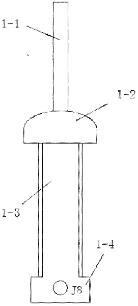
[0026] Such as Figure 4 As shown, the embodiment of the present invention is a common transceiver antenna applied to high-frequency ground wave radar, which includes a monopole transceiver common antenna body 1, a transceiver common antenna switch 2, a first electric tuning loop antenna 3, and a control pulse forming Circuit 4 , control voltage forming circuit 5 , first electric tuning loop antenna transceiver control circuit 6 , second electric tuning loop antenna 7 , and second electric tuning loop antenna transceiver control circuit 8 . The common antenna switch 2 for sending and receiving includes a transmitting branch switch 2-1 and a receiving branch switch 2-2; one input signal of the transmitting branch switch 2-1 comes from the transmitter, and the other input signal is output from the control pulse forming circuit 4 Control pulse...


PUM


Abstract

The invention relates to the technical field of radar detection, and in particular relates to a transmitting-receiving shared antenna applied to a high-frequency ground wave radar. The transmitting-receiving shared antenna disclosed by the invention is characterized by comprising a monopole transmitting-receiving shared antenna body, a transmitting-receiving shared antenna switch, a first electrical tuning ring antenna, a control impulse forming circuit, a control voltage forming circuit, a first electrical tuning ring antenna transmitting-receiving control circuit, a second electrical tuning ring antenna and a second electrical tuning ring antenna transmitting-receiving control circuit. By using the transmitting-receiving shared antenna, the problems that because the occupied area of the antenna system of the ground wave radar is large, a radar target is large and easy to damage, an ideal erecting field is not easily found and the like can be solved.

Description

technical field [0001] The invention relates to the technical field of radar detection, in particular to a common antenna for transmitting and receiving applied to high-frequency ground wave radar. Background technique [0002] High-frequency ground wave radar detects ocean state parameters or detects moving targets on the sea surface. There are currently two forms of its transmitting and receiving antennas. One receiving antenna is an array phased array antenna, and the transmitting antenna is a Yagi antenna. The ground area is wide, generally ranging from 300 meters to 1,000 meters, and is vulnerable to damage. The other is a compact antenna that uses a so-called monopole crossed-loop antenna combined with a monopole and two mutually orthogonal loop antennas. The transmitting antenna is also a Yagi antenna. figure 1 is a schematic diagram of a phased array radar receiving antenna in the prior art; figure 2 It is a schematic diagram of monopole cross receiving and transm...

Claims


Application Information

Patent Timeline
IPC IPC(8): H01Q21/00
Inventor 石振华吴世才徐新军杨振卫赵华志石新智
Owner WUHAN DEVICES ELECTRONICS TECH CO LTD
Why Eureka
Try Eureka