Sine wave disk type permanent magnet generator with novel magnetic pole structure

A technology for permanent magnet generators and disk generators, which is applied in the direction of magnetic circuit shape/style/structure, electrical components, electromechanical devices, etc. It can solve the problems of low utilization rate of iron core and difficult cooling of motors, so as to improve efficiency and simplify Installation and fixing methods, the effect of reducing manufacturing difficulty and cost

Inactive Publication Date: 2012-06-20
中国船舶重工集团公司第七一二研究所
View PDF2 Cites 10 Cited by
  • Summary
  • Abstract
  • Description
  • Claims
  • Application Information

AI Technical Summary

Problems solved by technology

[0002] With the development of motor technology, people have gradually realized that ordinary radial flux motors have some weaknesses that cannot be overcome by their own structure, such as difficult cooling of the motor and low utilization of the iron core.

Method used


Image

  • Sine wave disk type permanent magnet generator with novel magnetic pole structure
  • Sine wave disk type permanent magnet generator with novel magnetic pole structure
  • Sine wave disk type permanent magnet generator with novel magnetic pole structure

Examples


Embodiment 1

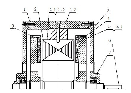
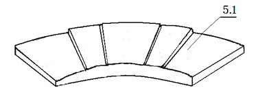
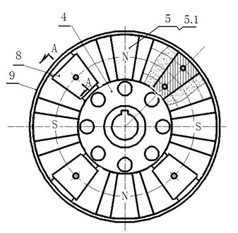
[0029] Such as figure 1 , 2 , 3, and 4, a sine wave disc permanent magnet generator with a new magnetic pole structure, including a base 1, a stator disc 2, a rotor disc 4 installed on both sides of the stator disc 2, fixed on the rotor disc 4 The magnetic pole 5 on the top, and the end cover 3, the rotating shaft 6 and the bearing 7; the magnetic pole 5 is composed of an even number of fan-shaped pole pieces 5.1 fixed on the rotor disk 4; as image 3 As shown, there are four fan-shaped pole pieces 5.1 in this embodiment; the fan-shaped pole pieces 5.1 are evenly distributed around the center of the rotor disk 4 along the circumference and fixed on the side of the rotor disk 4 facing the stator disk 2; figure 2 As shown, the side profile of each fan-shaped pole piece 5.1 facing the side of the stator plate 2 is stepped, and the middle of the ladder shape is a high step, and it descends symmetrically to both sides to a low step; two adjacent fan-shaped pole pieces 5.1 The di...

Embodiment 2

[0031] The difference from the first embodiment above is that the sector-shaped pole piece 5.1 has three steps, and the arc lengths of the symmetrical low steps on both sides of the middle high step are half of the arc length of the middle high step. When the arc lengths of the symmetrical low steps on both sides of the middle high step are equal to the arc length of the middle high step, it is a new embodiment.

Embodiment 3

[0033] Different from the above-mentioned embodiment 1, the sector-shaped pole piece 5.1 has 9 steps, wherein the arc lengths of the symmetrical low steps located at both ends are respectively equal to the arc lengths of the middle high steps, and the arc lengths of each of the remaining symmetrical low steps are respectively Half the arc length of the middle high step. When the arc length of each symmetrical low step is equal to the arc length of the middle high step, it is a new embodiment.

[0034] Figure 5 with Figure 7 Respectively, the no-load back EMF waveform calculated by simulation and the measured no-load back EMF waveform, Image 6 with Figure 8 The simulated load current waveform and the measured load current waveform are respectively. The comparison between the simulated calculation and the experimental test waveform shows that the amplitude and waveform of the simulated no-load back EMF waveform and the load current waveform are very close to the experimen...


PUM


Abstract

The invention relates to a sine wave disk type permanent magnet generator with a novel magnetic pole structure, which is particularly suitable for a disk type permanent magnet generator for the power generation of ships. The generator comprises a base, a stator disk, a rotor disk, a magnetic pole fixed on the rotor disk, an end cover, a rotation shaft and a bearing, wherein the magnetic pole consists of an even number of sector pole blocks fixed on the rotor disk; the sector pole blocks are uniformly distributed along the circumference around the center of the rotor disk and fixed on one side of the rotor disk facing to the stator disk; the side surface of one side of each sector pole block facing to the stator disk is in a step shape; a high step is arranged in the middle of the step shape, and low steps are symmetrically and gradually lowered toward the two sides; distance between two adjacent sector pole blocks is equal; the stator disk comprises a stator core and a stator winding; and the stator winding is a centralized integral pitch winding. The sine wave disk type permanent magnet generator with a novel magnetic pole structure, provided by the invention, has the advantages that: the generator has an air-gap flux density waveform with a relatively low sine aberration rate and a back-electromotive force waveform, the motor efficiency is improved, the magnetic pole is simple and convenient to mount and fix, and the wire insertion difficulty of the winding and the motor manufacturing cost are reduced.

Description

technical field [0001] The invention relates to a sine wave disc type permanent magnet generator with a novel magnetic pole structure, which is especially suitable for the disc type permanent magnet generator for ship power generation. Background technique [0002] With the development of motor technology, people have gradually realized that ordinary radial flux motors have some weaknesses that cannot be overcome by their own structure, such as difficult cooling of the motor and low utilization of the iron core. The air gap of the disc permanent magnet motor is planar, and the air gap magnetic field is axial, so it is also called an axial magnetic field motor. The disc permanent magnet motor effectively utilizes the space from the inner diameter of the stator core to the rotating shaft, thereby greatly shortening the axial dimension of the motor. Compact, the torque density can be increased by about 20%, and the disc motor has become one of the hot research objects in the f...

Claims


Application Information

Patent Timeline
Patent Type & Authority Applications(China)
IPC IPC(8): H02K16/02H02K1/27
Inventor 吴海鹰郝清亮杨德望
Owner 中国船舶重工集团公司第七一二研究所
Why Eureka
Try Eureka