Stem guide apparatus for use with fluid valve actuators

A technology for guiding devices and actuators, applied in fluid pressure actuating devices, valve devices, valve operation/release devices, etc., which can solve problems such as damage, friction, curling, and reduction of effective diaphragm area

Active Publication Date: 2012-06-20
FISHER CONTROLS INT LLC
View PDF10 Cites 2 Cited by
  • Summary
  • Abstract
  • Description
  • Claims
  • Application Information

AI Technical Summary

Problems solved by technology

However, this movement or displacement of the spring may cause the diaphragm plate to engage the inner surface of the actuator housing, causing friction and / or warping, deforming or damaging the diaphragm and reducing the effective diaphragm area
Reducing the effective diaphragm area of ​​the diaphragm reduces the net amount of torque the actuator provides to the flow control member when the flow control member is engaged with the valve seat, thereby reducing the performance of the fluid control valve

Method used


Image

  • Stem guide apparatus for use with fluid valve actuators
  • Stem guide apparatus for use with fluid valve actuators
  • Stem guide apparatus for use with fluid valve actuators

Examples


Embodiment Construction

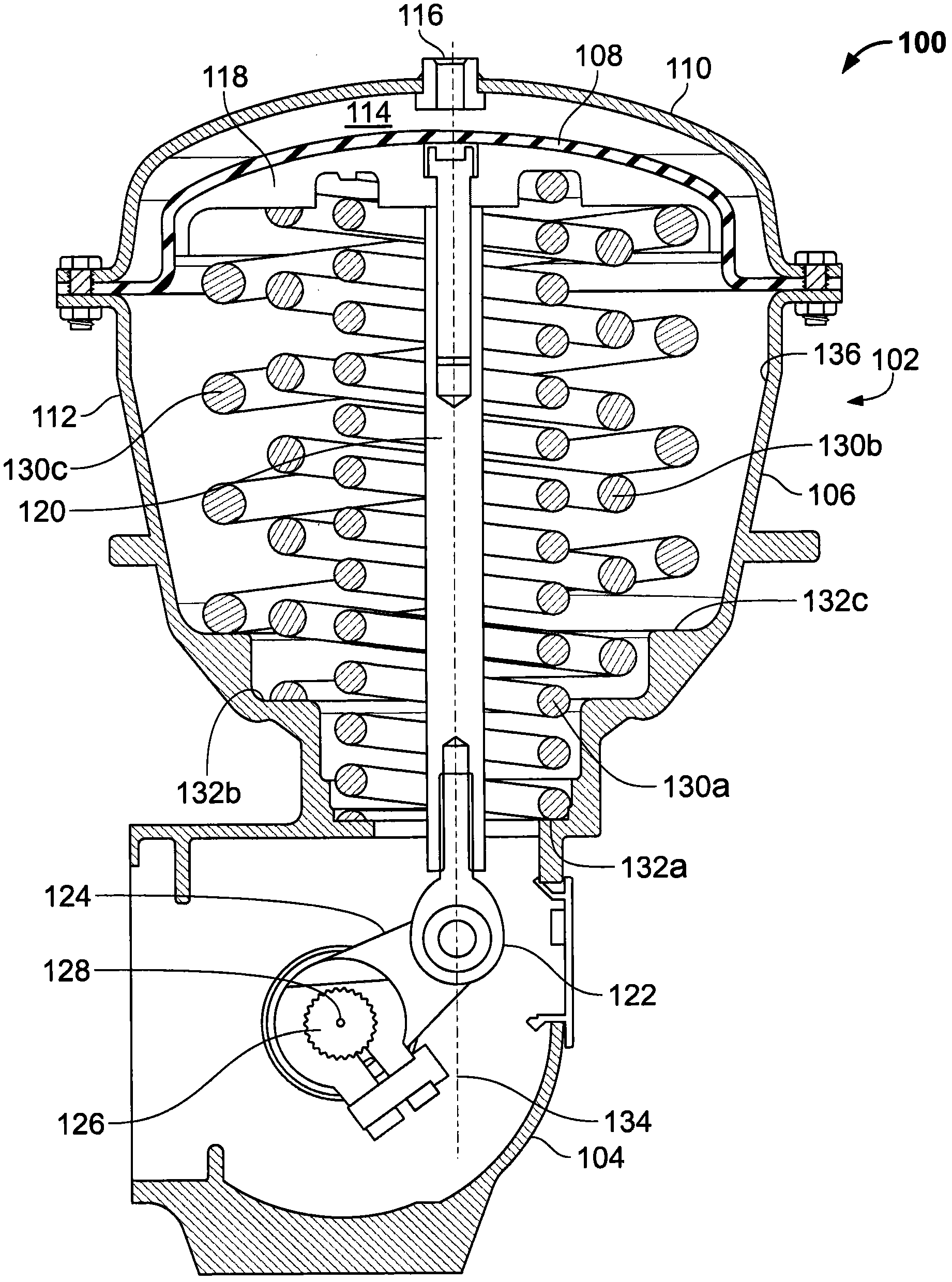
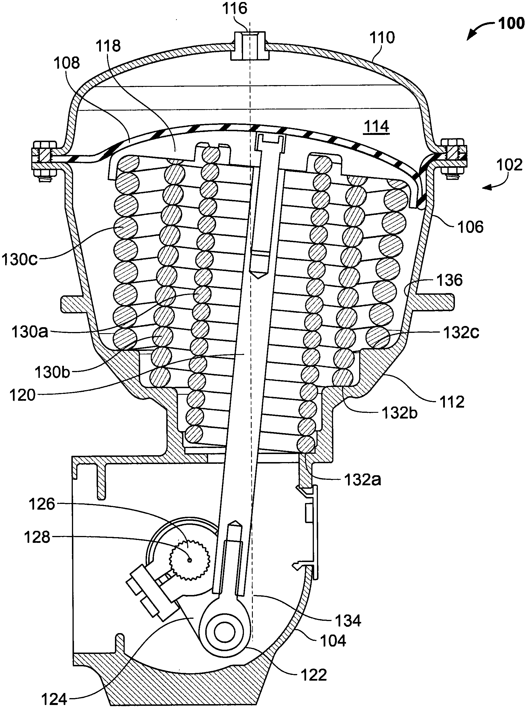
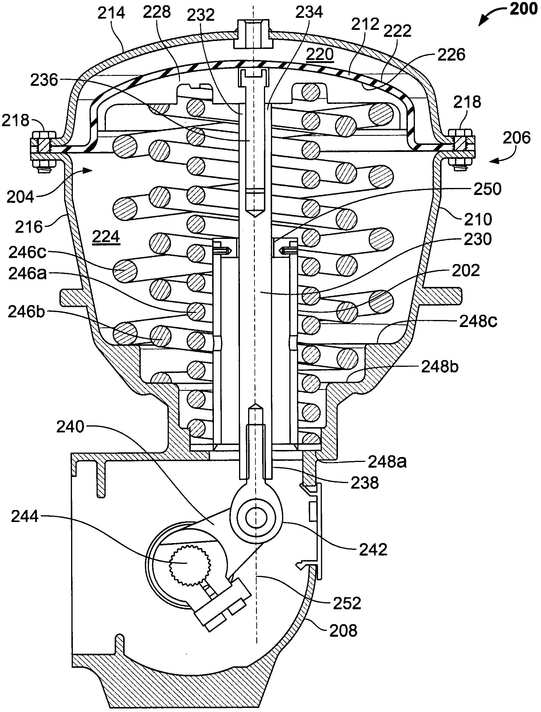
[0013] Generally, the exemplary actuator stem guides described herein prevent a fluid control valve diaphragm assembly (e.g., diaphragm and / or diaphragm plate) from contacting or engaging an interior surface or sidewall of the actuator housing to Prevents actuator degradation and / or damage to the diaphragm assembly during operation. In particular, an exemplary actuator rod guide may include a housing disposed within the actuator housing that includes an aperture or bearing surface to slidably receive and / or guide the actuator rod. In one embodiment, at least a portion of the actuator rod guide housing and / or the bearing surface is made of a material such as Delrin (Delrin), polytetrafluoroethylene (PTFE), ultra-high molecular weight polyethylene (UHMWPE) and other low friction materials to reduce friction when the actuator rod slides relative to the actuator rod guide. In operation, the actuator rod guide applies a force to the actuator rod, thereby guiding and / or substantial...


PUM


Abstract

Actuator stem guide apparatus for use with fluid valve actuators are described. An example actuator stem guide apparatus includes a base having an opening ( 310 ) to allow an actuator stem ( 230 ) of the fluid valve actuator to tilt or lean within the base to enable a lever of the fluid valve actuator to rotate and a guide receiving area adjacent the opening of the base. A guide ( 304 ) is coupled to the guide receiving area and the guide has a bearing surface ( 316 ) to slidably engage the actuator stem to limit lateral movement of a diaphragm assembly relative to a longitudinal axis of the opening to prevent the diaphragm assembly from engaging an inner surface of an actuator housing as the actuator stem moves between a first position and a second position.

Description

technical field [0001] The present invention relates generally to a fluid valve actuator, and more particularly to a rod guide for a fluid valve actuator. Background technique [0002] Automated control valves, such as rotary control valves, are often used in process control plants or systems to control the flow of process fluids. Swing control valves typically include an actuator (eg, a pneumatic actuator, an electric actuator, a hydraulic actuator, etc.) operatively coupled by a lever to a valve shaft extending from the rotary valve. A lever converts linear displacement of the actuator into rotational displacement of the valve shaft. Thus, rotation of the lever rotates the valve shaft and a flow control member (e.g., disc, ball, etc.) coupled to the valve shaft relative to the valve seat to allow fluid flow through the valve (e.g., an open position) or to restrict flow through the valve. The fluid flow of a valve (eg closed position). In operation, the actuator rod may ...

Claims


Application Information

Patent Timeline
Patent Type & Authority Applications(China)
IPC IPC(8): F16K31/165
CPCF16K31/1655F15B15/10Y10T137/5109
Inventor B·Q·莱杰T·F·杰克逊
Owner FISHER CONTROLS INT LLC
Why Eureka
Try Eureka