
Air pressure circuit of tire testing device, tire testing device, and tire testing method

A test device and tire technology, applied in the direction of automobile tire testing, etc., can solve the problems of unrealistic adjustment, low responsiveness, and high price of tire test device, and achieve the effect of suppressing air pressure fluctuation and high-precision test

Inactive Publication Date: 2015-01-07
KOBE STEEL LTD
View PDF7 Cites 0 Cited by
  • Summary
  • Abstract
  • Description
  • Claims
  • Application Information

AI Technical Summary

Problems solved by technology

This servo-type pressure regulating valve has excellent pressure regulation accuracy, but has low responsiveness and high price
Therefore, even if the servo-type pressure regulating valve can cope with gentle and steady changes in air pressure, it does not have the responsiveness to timely adjust the air pressure in the tire within the tire test time of only about 1 second.
In addition, if an expensive component such as a servo-type pressure regulating valve is used, there is also a problem that the price of the tire testing device is too high
Therefore, as in Patent Document 2, it is not realistic to adjust the air pressure in the tire that fluctuates during the tire test in a tire testing device using a servo pressure regulating valve.

Method used


Image

  • Air pressure circuit of tire testing device, tire testing device, and tire testing method
  • Air pressure circuit of tire testing device, tire testing device, and tire testing method
  • Air pressure circuit of tire testing device, tire testing device, and tire testing method

Examples


no. 1 Embodiment approach

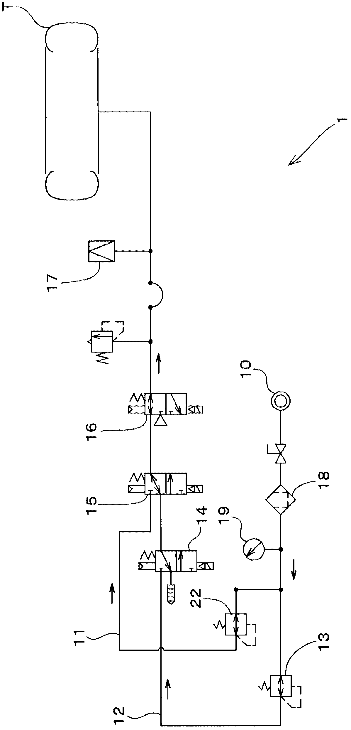
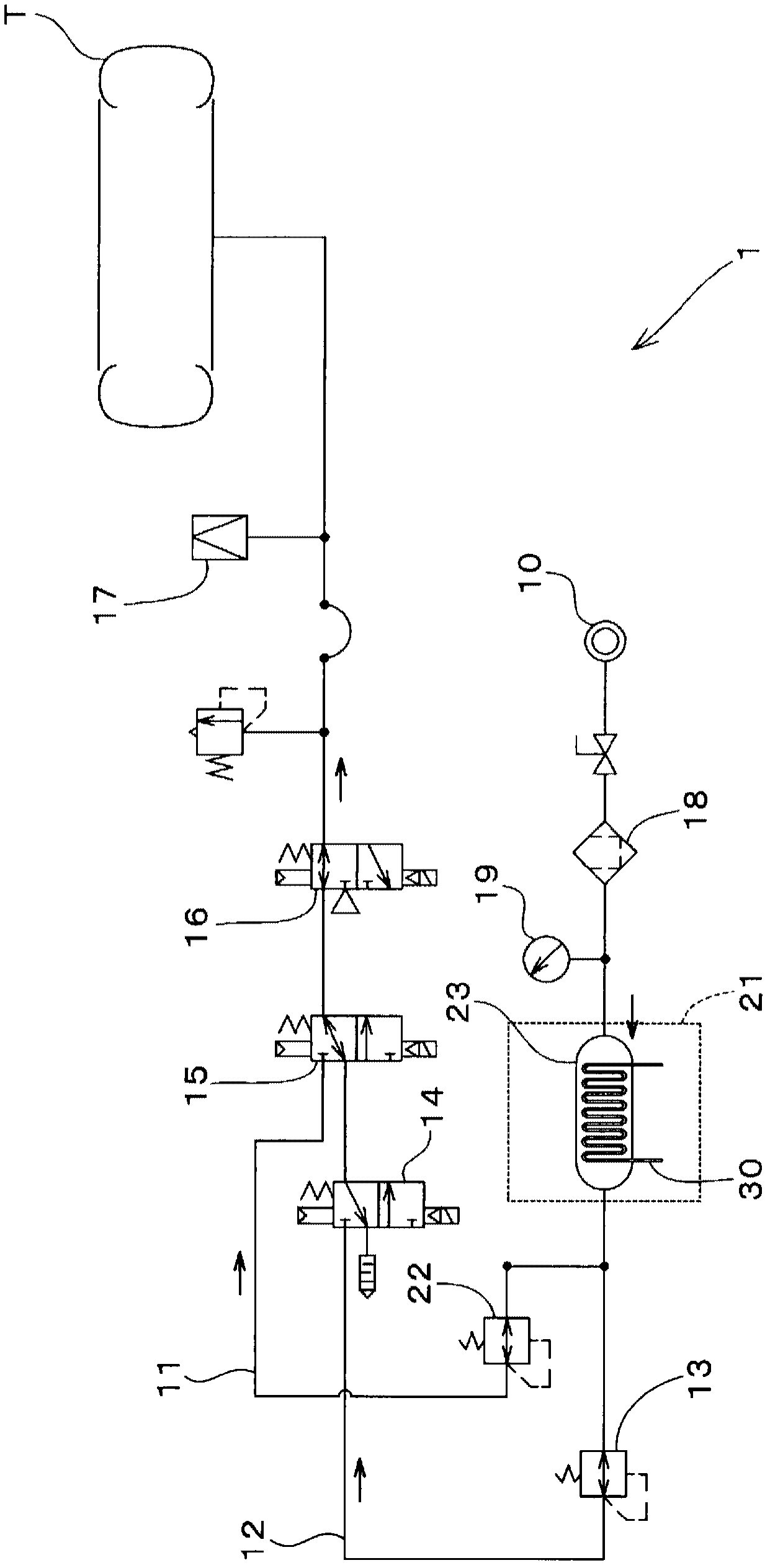
[0042] A pneumatic circuit 1 and a tire testing device 2 provided with the pneumatic circuit 1 according to the first embodiment will be described with reference to the drawings.

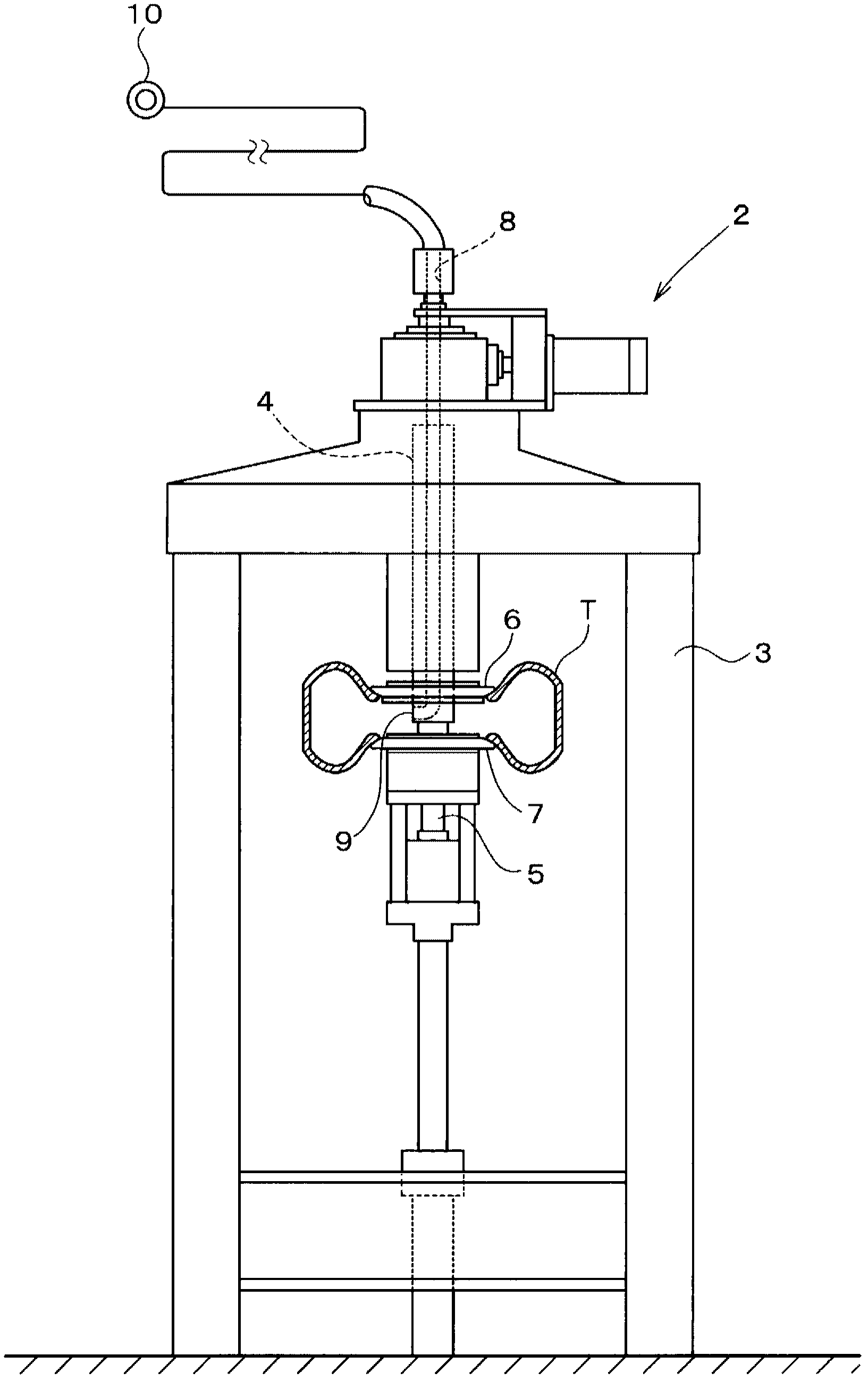
[0043] The tire testing device 2 of the present invention performs product inspection such as a uniformity test on the tire T completed in the form of a product. In this embodiment, a uniformity machine is used as the tire testing device 2 . This tire testing device 2 has, for example, figure 1 configuration as shown.

[0044] Such as figure 1 As shown schematically, the tire testing device 2 includes a frame 3 arranged in a tower shape on the ground, a set of upper and lower tire shafts 4, 5 installed on the frame 3, and a tire T fixed on these tire shafts 4, 5. The rims 6, 7. These tire shafts 4, 5 are provided rotatably around the vertical shaft. In addition, on the side of the tire T fixed by the rims 6 and 7, a roller (not shown) whose outer peripheral surface forms a simulated road surfac...

no. 2 Embodiment approach

[0105] Next, the pneumatic circuit 1 of the second embodiment and the tire testing device 2 including the same will be described.

[0106] Such as Figure 4 As shown, the pneumatic circuit 1 of the second embodiment differs from the first embodiment in that it includes an exhaust unit 24 as the air temperature adjustment mechanism 21 . The exhaust unit 24 exhausts the air in the storage tank 23 to the outside before supplying it to the tire T at the bead pressure to cause adiabatic expansion.

[0107] In addition, in the air pressure circuit 1 according to the second embodiment, the air supply source 10 can supply air at a pressure (for example, about 800 kPa) higher than the bead air pressure.

[0108] The air temperature adjustment mechanism 21 includes a storage tank 23 disposed downstream of the pressure gauge 19 and upstream of a branch point of the bead seat system 11 and the test system 12 . The storage tank 23 is provided with a relief valve 33 via a shutoff valve 32...


PUM


Abstract

Disclosed is a tire testing device capable of suppressing variations in air pressure occurring during tire testing by adjusting the temperature of air supplied to a tire. Specifically disclosed is an air pressure circuit (1) of a tire testing device (2), which comprises an air supply source (10) that supplies air to a tire (T) mounted between a pair of rims (6, 7) and a pressure adjusting valve (13) that adjusts the pressure of the air supplied from the air supply source (10) to the tire (T) to a bead air pressure for expanding the tire (T) so that the tire (T) can be mounted on the rims (6, 7) or to a test air pressure that is lower than the bead air pressure and that is used during tire testing. The air pressure circuit (1) of the tire testing device (2) also comprises an air temperature adjusting mechanism (21) that can cool the air supplied to the tire (T) at the bead air pressure such that the temperature thereof is reduced to a temperature lower than that of the outside air.

Description

technical field [0001] The present invention relates to a pneumatic circuit used in a tire testing device such as a tire uniformity machine, a tire testing device provided with the pneumatic circuit, and a tire testing method for performing a tire test using the pneumatic circuit. Background technique [0002] Conventionally, for tires completed in the form of products, a tire test (uniformity inspection) is performed to check the uniformity, etc., to determine whether it is acceptable or not. When testing the uniformity of, for example, a tire for a passenger car, the tire test is performed using a testing device roughly as shown in Patent Document 1 according to the following procedure. [0003] The tire testing apparatus of Patent Document 1 includes an air pressure circuit that adjusts the compression of compressed air supplied from a factory air source, supplies it to a tire supported on a rim, and performs a tire test after inflating the tire. This air pressure circui...

Claims


Application Information

Patent Timeline
Patent Type & Authority Patents(China)
IPC IPC(8): G01M17/02
CPCG01M17/02
Inventor 冈田彻村上将雄本家浩一
Owner KOBE STEEL LTD
Learn More