
A universal device for automatic clamping for accurate testing of microwave modules

A general-purpose device and microwave technology, which is applied in the direction of measuring devices, measuring device casings, and parts of electrical measuring instruments, can solve problems such as difficulty in engineering application, lack of versatility, and difficulty in achieving test accuracy, achieving low cost, The design is simple and low-cost, and the effect of high-precision testing is realized

Active Publication Date: 2022-05-17
LEIHUA ELECTRONICS TECH RES INST AVIATION IND OF CHINA
View PDF8 Cites 0 Cited by
  • Summary
  • Abstract
  • Description
  • Claims
  • Application Information

AI Technical Summary

Problems solved by technology

[0005] Main disadvantage 1: It is necessary to frequently change tooling and connections for different test modules and test items, it is difficult to ensure the consistency of clamping, and it is difficult to achieve test accuracy
[0006] Main disadvantage 2: It is difficult to realize automatic clamping with high precision and high reliability;
[0007] The main disadvantage three: it is not universal, and it is difficult to meet the accurate clamping test of different module variants and variant parameters;
[0008] Main disadvantage 4: The complexity and cost of research and development are very high, real-time measurement inspection is required, and engineering application is difficult to realize;
[0009] Main disadvantage 5: It is difficult to realize the automatic reconfiguration test of the next clamping channel, instrument and drive of the standard interface, the test efficiency is low, and the frequent state changes make it difficult to guarantee the test consistency

Method used


Image

  • A universal device for automatic clamping for accurate testing of microwave modules
  • A universal device for automatic clamping for accurate testing of microwave modules
  • A universal device for automatic clamping for accurate testing of microwave modules

Examples


Embodiment Construction

[0035] In order to make the objectives, technical solutions and advantages of the present invention clearer, the technical solutions in the embodiments of the present invention will be described in more detail below in conjunction with the drawings in the embodiments of the present invention. In the drawings, the same or similar reference numerals denote the same or similar elements or elements having the same or similar functions throughout. The described embodiments are some, but not all, embodiments of the invention. The embodiments described below by referring to the figures are exemplary and are intended to explain the present invention and should not be construed as limiting the present invention. Based on the embodiments of the present invention, all other embodiments obtained by persons of ordinary skill in the art without creative efforts fall within the protection scope of the present invention. Embodiments of the present invention will be described in detail below ...


PUM


Abstract

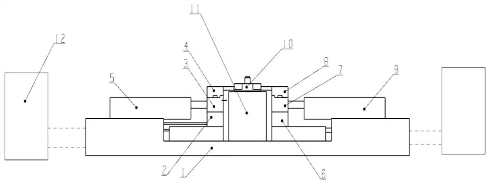
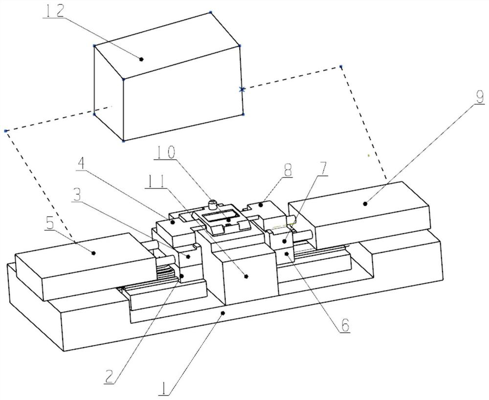
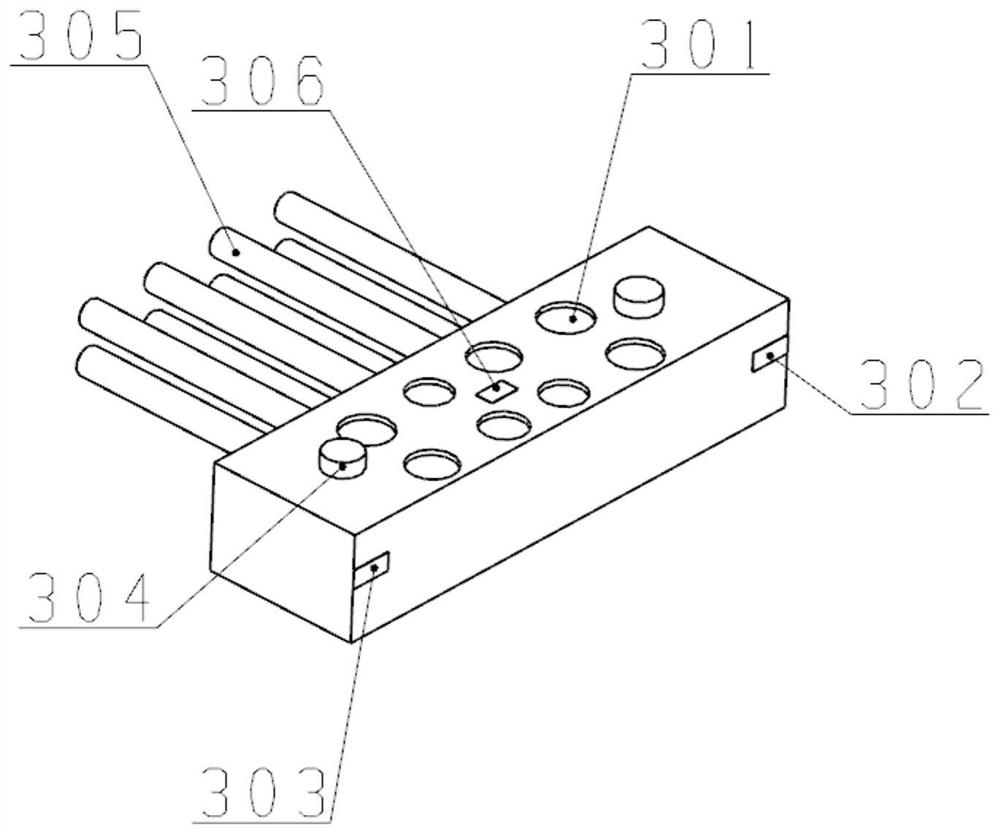
The invention provides a universal automatic clamping device for accurate testing of microwave modules. The microwave module is installed on the universal automatic clamping device through a control system, which mainly includes a loading and positioning platform (11), a first rotation connecting tooling (4) and second switching tooling (8), wherein, the first tooling installation platform (3) and the second tooling installation platform (7) are respectively arranged on respective slide rails, and are controlled by the cylinder Drive abutting against and away from the integrated part of the tooling (10), and then cooperate with the special transfer tooling, with the help of the robot and the control system, the automatic clamping, connection, positioning, state perception, channel changing, driving and Change the test configuration. The reconfigurable universal radio frequency interface and definable control interface designed by the present invention do not require connectors when testing various modules, which eliminates the problems of uncontrollable errors caused by frequent replacement of connectors, and improves the research and development level of components and Reduce R&D and production costs.

Description

technical field [0001] The invention belongs to the field of intelligent manufacturing and is applied to intelligent debugging and testing of micro-assembled electronic products, in particular to a universal automatic clamping device for accurate testing of microwave modules. Background technique [0002] With the development of microelectronic technology and micro-assembly technology, high-density electronic products based on micro-assembly, such as T / R components, have been widely used in various fields such as aviation, aerospace, and communication. However, the continuous improvement of the integration of microwave modules has brought great challenges to the high-precision testing and debugging of dozens of parameters. To achieve high-precision and efficient testing and debugging, the test fixture, radio frequency and control interface connection of the microwave module Repeat error and reliability control become one of the keys. The clamping performance of the module di...

Claims


Application Information

Patent Timeline
Patent Type & Authority Patents(China)
IPC IPC(8): G01R1/04
CPCG01R1/0416G01R1/0425
Inventor 鄢学全吴沂骞
Owner LEIHUA ELECTRONICS TECH RES INST AVIATION IND OF CHINA
Learn More