Eureka AIR delivers breakthrough ideas for toughest innovation challenges, trusted by R&D personnel around the world.

Transmission structure of stone sawing machine

A transmission structure, technology of stone sawing machine, applied in the direction of transmission device, gear transmission device, mechanical equipment, etc., can solve the problems of inconsistent wear of left and right belts, inconvenient maintenance work, large area of ​​stone sawing machine, etc. The effect of maintenance work, simple and reasonable structure, and reduced floor space

Inactive Publication Date: 2012-06-27
佛山市顺德区悍天睿数控机械有限公司
View PDF5 Cites 2 Cited by
  • Summary
  • Abstract
  • Description
  • Claims
  • Application Information

AI Technical Summary

Problems solved by technology

However, due to the use of belt transmission in its transmission structure, its volume is relatively large, which is not convenient for daily maintenance. At the same time, the stone saw machine occupies a large area. After long-term use, the wear of the left and right belts is inconsistent, which affects the consistency of its speed.

Method used


Image

  • Transmission structure of stone sawing machine
  • Transmission structure of stone sawing machine
  • Transmission structure of stone sawing machine

Examples


Embodiment Construction

[0014] The present invention will be further described below in conjunction with the accompanying drawings and embodiments.

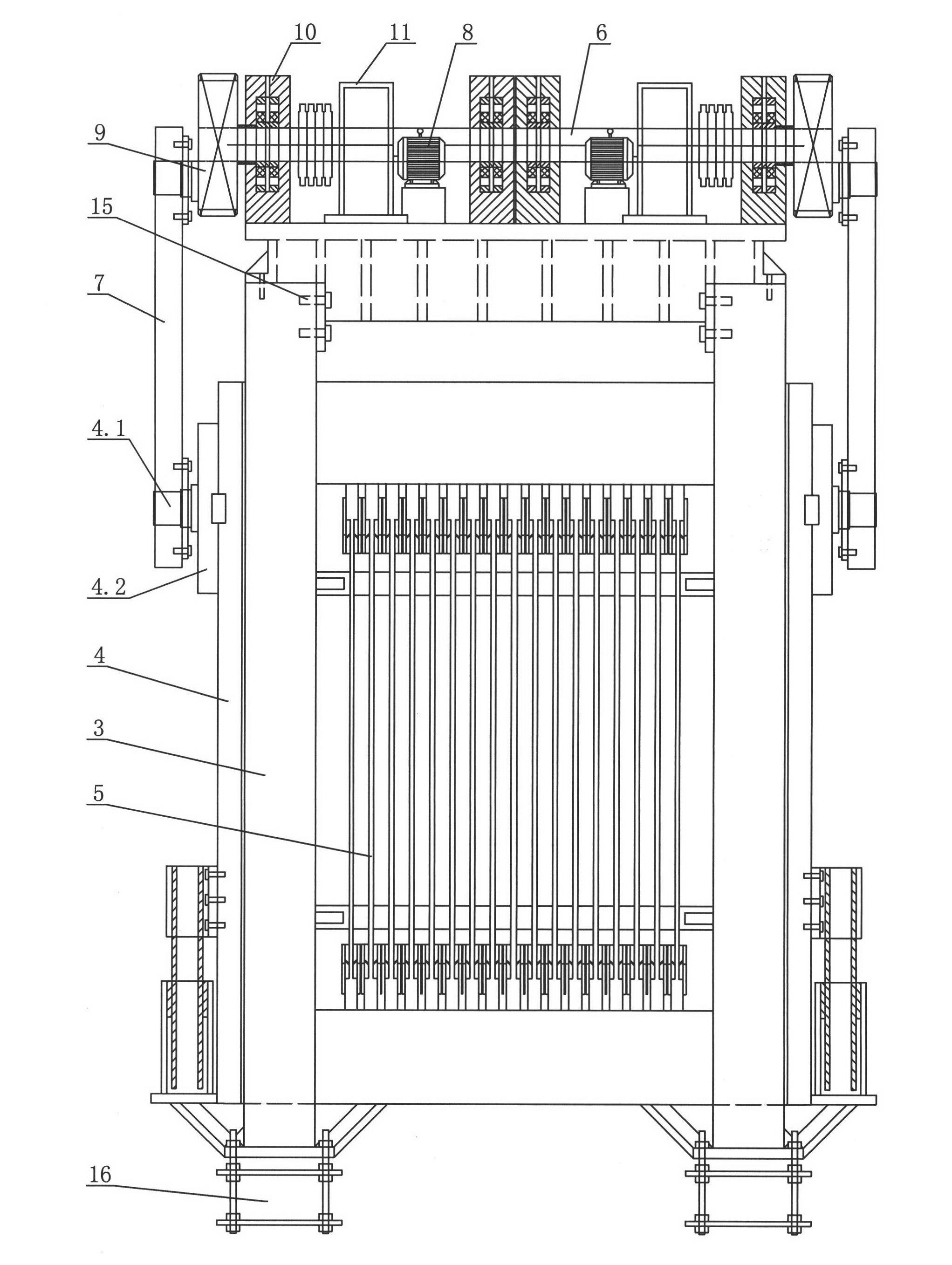
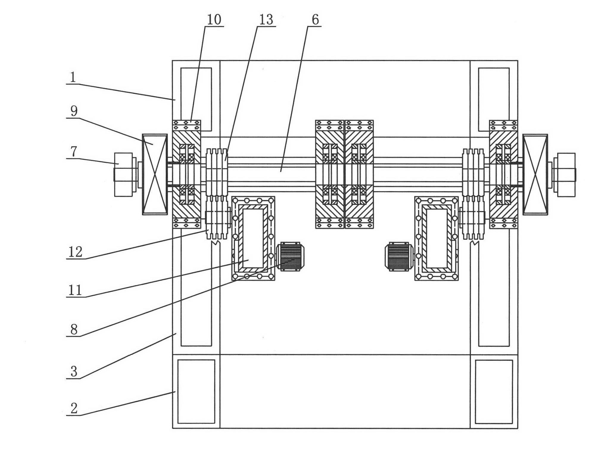
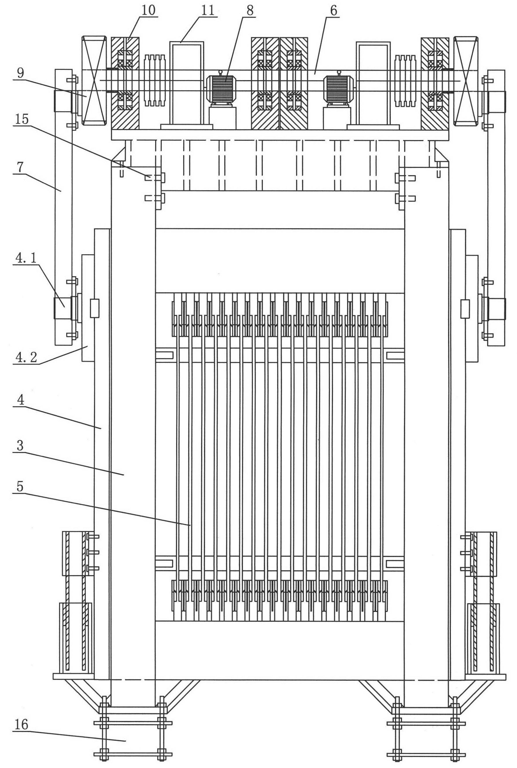
[0015] see Figure 1-Figure 2 , the transmission structure of this stone sawing machine includes a top frame 3 arranged between the front column 1 and the rear column 2, the saw frame 4 is located under the top frame 3, the saw frame 4 is provided with several saw blades 5, and the top of the machine The top of the frame 3 is provided with a transmission mechanism that can drive the saw frame 4 to move back and forth up and down.

[0016] The transmission mechanism includes a motor 8 and a main shaft 6 which are arranged on the top of the machine top frame 3 and are in transmission connection with each other. The main shaft 6 is connected with the saw frame 4 through an eccentric block 9 .

[0017] The main shaft 6 straddles both sides of the top of the top frame 3, and the top frame 3 is provided with several bearing blocks 10 supporting the main shaf...


PUM


Abstract

A transmission structure of a stone sawing machine comprises a machine upper frame arranged between a front column and a back column. A saw frame is arranged below the machine upper frame and provided with a plurality of saw blades, and a transmission mechanism capable of driving the saw frame to do vertical back and forth movement is arranged at the top of the machine upper frame of the transmission structure. The transmission mechanism comprises motors and a main shaft which are mutually connected in transmission and arranged at the top of the machine upper frame. The main shaft straddles two sides of the top of the machine upper frame, a plurality of bearing pedestals bearing the main shaft are arranged on the machine upper frame, and eccentric blocks are respectively connected to outer end portion of the main shaft. The motors are divided into two groups, respectively arranged on the two sides of the top of the machine upper frame, and respectively connected with two ends of the main shaft in a transmission mode through speed changing boxes. The transmission structure of the stone sawing machine is arranged on a platform at the top of the machine, which enables floor space of the stone sawing machine to be substantially decreased, the transmission structure is high in transmission efficiency and good in synchronization performance due to the fact that the transmission mechanism adopts an all-gear drive mode, and the transmission structure is small in volume and convenient for overhaul and maintenance work in the future.

Description

technical field [0001] The invention relates to a stone sawing machine, in particular to a transmission structure of the stone sawing machine. Background technique [0002] On September 7, 2011, I disclosed a main shaft structure of a large-scale stone sawing machine in Chinese Patent Document No. CN102172987A. The large-scale stone sawing machine includes a saw frame that slides up and down between the front column and the rear column, and the saw frame Several saw blades / strips are arranged on the top; the main transmission structure includes a main shaft connected to the saw frame, and the main shaft is connected to the driving motor; the main shaft is connected to the saw frame through an eccentric block and a connecting rod. The left and right sides of the saw frame are respectively connected to the driving motor through the main shaft; the speed of the two main shafts is the same. The main shaft is driven by the eccentric block and connecting rod and the saw frame to ...

Claims


Application Information

Patent Timeline
Patent Type & Authority Applications(China)
IPC IPC(8): B28D1/02F16H1/02
Inventor 周金生
Owner 佛山市顺德区悍天睿数控机械有限公司
Why Eureka
Eureka Blog
Learn More