Mounting structure of pin shaft, jib structure of engineering machinery and concrete pumping device

A technology for installation structures and engineering machinery, which is applied in the direction of mechanical equipment, shafts, bearings, pivots, etc., and can solve problems such as large deformation, poor stability of pin-shaft connections, and affecting assembly dimensions

Active Publication Date: 2013-06-05
ZOOMLION HEAVY IND CO LTD
View PDF5 Cites 0 Cited by
  • Summary
  • Abstract
  • Description
  • Claims
  • Application Information

AI Technical Summary

Problems solved by technology

[0003] In this installation structure in the prior art, since only two ends of the pin shaft are supported by the connecting rod 62, the overall deformation of the pin shaft will be relatively large during operation, and the assembly size will be affected, making the connection stability of the pin shaft poor.
In order to reduce the deformation of the pin shaft, the technical solution of increasing the diameter of the pin shaft is usually used in the prior art. However, with the development of construction machinery such as pump trucks to the direction of long arms and large-scale, the pin shaft as a connecting piece needs to be The lighter the weight, the better. If the diameter of the pin shaft is increased, the pin shaft will become heavier, which is not good for the weight reduction of the jib and other equipment.

Method used


Image

  • Mounting structure of pin shaft, jib structure of engineering machinery and concrete pumping device
  • Mounting structure of pin shaft, jib structure of engineering machinery and concrete pumping device
  • Mounting structure of pin shaft, jib structure of engineering machinery and concrete pumping device

Examples


Embodiment Construction

[0044] Specific embodiments of the present invention will be described in detail below in conjunction with the accompanying drawings. It should be understood that the specific embodiments described here are only used to illustrate and explain the present invention, and are not intended to limit the present invention.

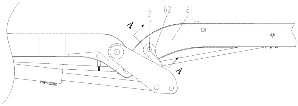
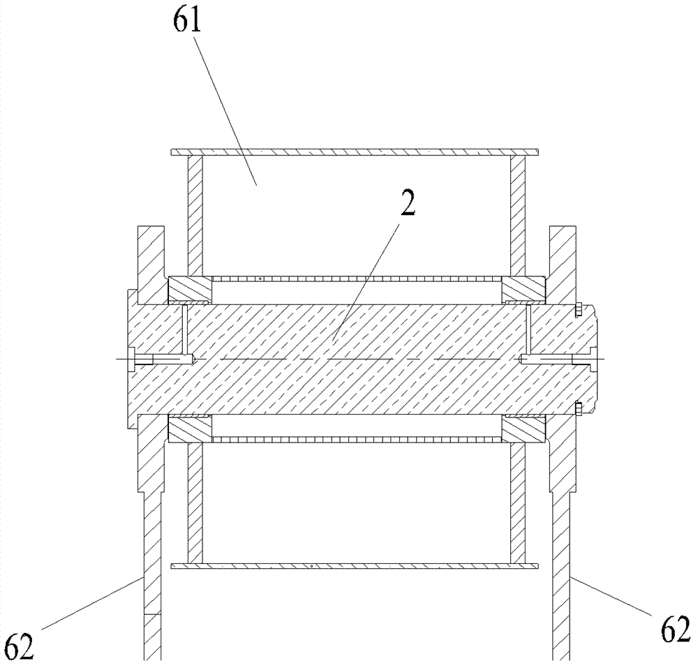
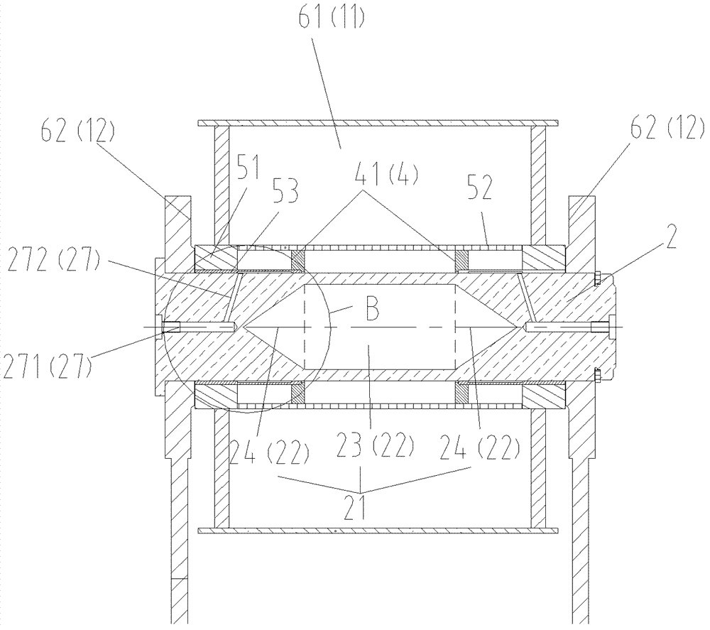
[0045] In order to overcome the problem of the mounting structure of the pin shaft in the prior art, such as Figure 3 to Figure 5 As shown, a pin installation structure is provided, including a connected object 1 and a pin shaft 2 passing through the connected object 1, the two ends of the pin shaft 2 are supported by the connected object 1, and the pin shaft installation structure also includes a support The supporting part 4 of the bearing pin 2 is located between the two supported ends of the pin shaft 2 .

[0046] Specifically, in the preferred embodiment of the present invention, in order to adapt to the articulation between the arm section 61 and the con...


PUM


Abstract

Disclosed is a shaft pin installation structure, comprising a connected item (1) and a shaft pin (2) passing through the connected item. The two ends of the shaft pin (2) are borne by the connected item. The structure also comprises a carrier (4) bearing the shaft pin (2), the carrier (4) being located between the two ends of the shaft pin (2) being borne, and the shaft pin (2) is provided with a weight-reducing and removing part (21). Further disclosed are a cantilever structure of engineering machinery using the shaft pin installation structure and concrete pumping equipment using the cantilever structure. Since a carrier is provided between the two ends of the shaft pin being borne, the load of the bending moment to which the shaft pin is subjected is distributed more rationally, thus when in operation, deformation is relatively small without affecting the assembly size, making the connection of the shaft pin more robust. Furthermore, since the shaft pin is provided with a weight-reducing and removing part, the weight of the shaft pin can be effectively reduced. In addition, a cantilever using this installation structure can also achieve reduced weight, improving the practical applicability thereof.

Description

technical field [0001] The invention relates to the field of pin shaft installation, in particular to a pin shaft installation structure, an engineering machinery boom structure using the mounting structure, and concrete pumping equipment using the boom structure. Background technique [0002] In various construction machinery such as concrete pumping equipment, the use of pin shafts for hinge connection is widely used, especially the foldable boom structure, which mainly includes the hinge connection between the arm and the arm, the hinge between the connecting rod and the arm Connection, etc., in which the hinge connection of two relatively rotating parts is realized by the pin shaft, and the load of one part is transferred to the other part. by figure 1 In the boom structure shown as an example, the boom section 61 and the connecting rod 62 are connected by the pin shaft 2, wherein the visible connecting rod 62 is an outer connecting rod, and there is another identical c...

Claims


Application Information

Patent Timeline
Patent Type & Authority Patents(China)
IPC IPC(8): F16C11/04F16C33/04F16N1/00E04G21/04
CPCF16C33/04F16C11/04E04G21/0445F16C11/045F16N1/00E04G21/04F16C11/02B66C23/68
Inventor 邝昊李乡安
Owner ZOOMLION HEAVY IND CO LTD
Why Eureka
Try Eureka