

Touch display device
A touch display device and display panel technology, applied in static indicators, optics, instruments, etc., can solve the problems of a decrease in the signal/noise ratio of a touch panel, poor sensing capability, and interference with a sensing pad sensing signal. , to achieve the effect of reducing signal interference problems, improving signal/noise ratio and sensing capability
- Summary
- Abstract
- Description
- Claims
- Application Information
AI Technical Summary
Problems solved by technology
Method used
Image

Examples
no. 1 example
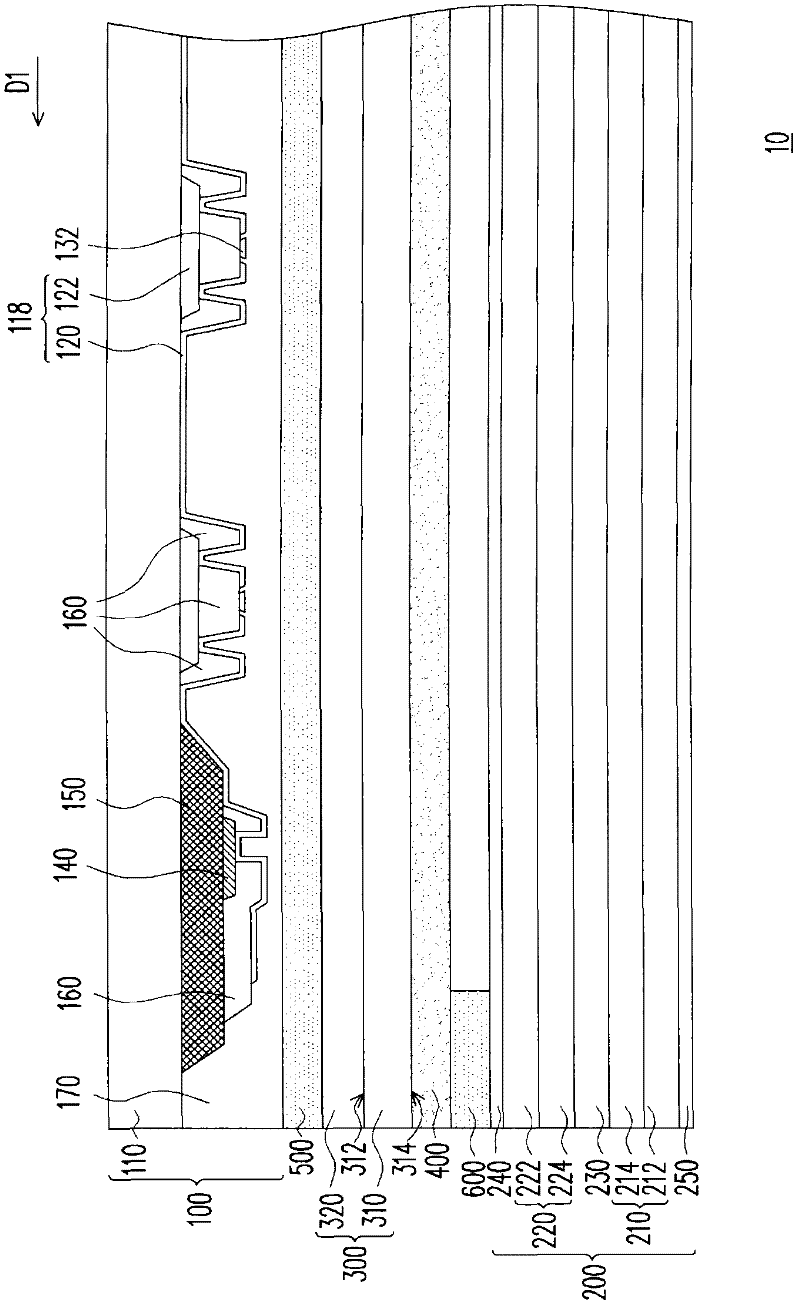
[0039] figure 1 It is a schematic cross-sectional view of the touch display device according to the first embodiment of the present invention. Please refer to figure 1 , the touch display device 10 includes a touch panel 100 , a display panel 200 , an explosion-proof film 300 and a transparent conductive layer 400 . The explosion-proof film 300 is disposed between the touch panel 100 and the display panel 200 . The transparent conductive layer 400 is disposed between the display panel 200 and the explosion-proof film 300 . In this embodiment, the touch display device 10 further includes a first adhesive layer 500 and a second adhesive layer 600 .
[0040] The touch panel 100, for example, includes a substrate 110 and a plurality of first sensing pads 120 disposed on the substrate 110, a plurality of second sensing pads (not shown), a plurality of first bridge lines 122, a plurality of second The bridge line 132 , the fan-out line 140 , the black frame 150 , the patterned p...
no. 2 example
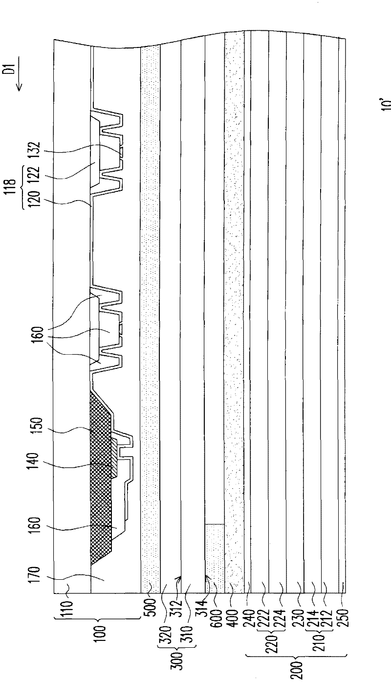
[0048] figure 2 It is a schematic cross-sectional view of a touch display device according to a second embodiment of the present invention. Components of the touch display device 10' and figure 1 The components and structures of the touch display device 10 are substantially the same, and the differences will be described below. In this embodiment, the transparent conductive layer 400 is disposed between the display panel 200 and the explosion-proof film 300 , and the transparent conductive layer 400 is disposed between the display panel 200 and the second adhesive layer 600 , for example. In this embodiment, the transparent conductive layer 400 is, for example, formed on the first polarizer 240 of the display panel 200 . Specifically, after disposing the transparent conductive layer 400 on the display panel 200, the explosion-proof film 300 and the touch panel 100 are bonded through the first adhesive layer 500, and then the explosion-proof film 300 and the touch panel 100 ...
no. 3 example
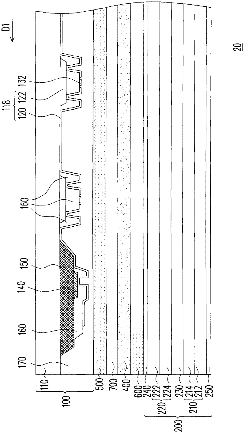
[0052] image 3 It is a schematic cross-sectional view of a touch display device according to a third embodiment of the present invention. Please refer to image 3 , the touch display device 20 includes a touch panel 100 , a display panel 200 , a transparent substrate 700 and a transparent conductive layer 400 . The transparent substrate 700 is disposed between the touch panel 100 and the display panel 200 . The transparent conductive layer 400 is disposed between the transparent substrate 700 and the display panel 200 . In this embodiment, the touch display device 20 further includes a first adhesive layer 500 and a second adhesive layer 600 . In this embodiment, the components of the touch panel 100 and the display panel 200 can refer to those described in the first embodiment, and will not be repeated here.
[0053] In this embodiment, the transparent conductive layer 400 is, for example, formed on the transparent substrate 700 . The transparent substrate 700 may be a ...
PUM
 Abstract
Description
Claims
Application Information