Large-flow annular experiment water tank

A large-flow, ring-shaped technology, applied in teaching models, educational appliances, instruments, etc., can solve the problems of small flow in the tank and the inability to contain vegetation, etc., and achieve the effect of low energy consumption

Active Publication Date: 2012-06-27
BEIJING WATER SCI & TECH INST
View PDF4 Cites 16 Cited by
  • Summary
  • Abstract
  • Description
  • Claims
  • Application Information

AI Technical Summary

Problems solved by technology

[0004] In order to overcome the shortcomings of the existing water tanks with low flow rate and the inability to realize hydraulic experiments with vegetation, the present invention provides a large-flow ring-shaped water tank. Accuracy of Indoor Hydraulic Experiments for Trees and Shrubs

Method used


Image

  • Large-flow annular experiment water tank
  • Large-flow annular experiment water tank
  • Large-flow annular experiment water tank

Examples


Embodiment 1

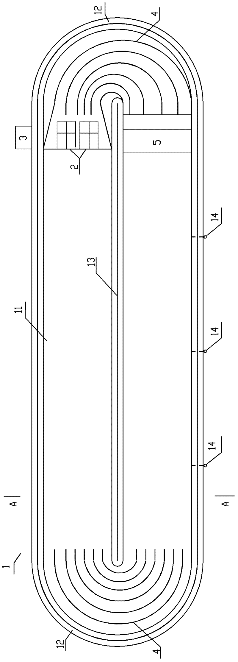
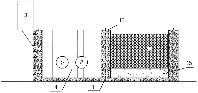
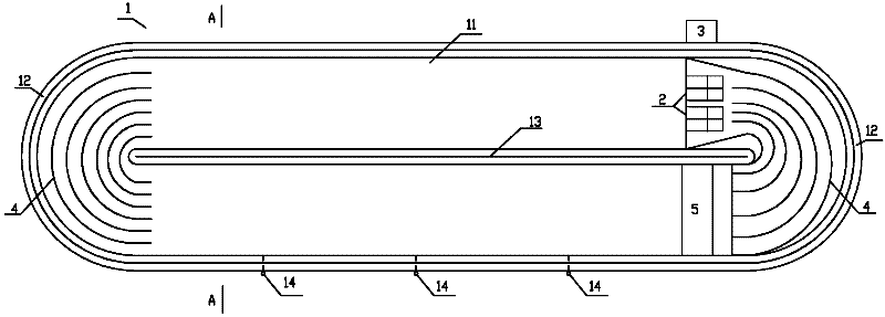
[0022] Such as figure 1 As shown, in a preferred embodiment of the present invention, the large-flow annular experimental water tank includes an annular tank 1 , a flow impeller 2 , a frequency converter 3 , a deflector 4 and a honeycomb flow stabilization grid 5 . The inner width of the annular groove 1 is 3m, and the depth is 2.7m. It consists of two straight sections 11 parallel to each other and two curved sections 12 connecting the two straight sections. The straight section is the test section. In the present embodiment, the two straight parts are separated by a partition wall 13, the length of the straight part is 19m, and the gravel riverbed backfill 15 of Yongding River with a thickness of 0.5m is laid at the bottom. Both bends are semicircular. The impeller is a cylindrical motor with an external impeller, and the diameter of the impeller is 615mm. In order to meet the flow requirement, two flow impellers are used with a total motor power of 35-75kw. The flow pushe...

Embodiment 2

[0024] Embodiment 2 Contains the riverbed roughness flume experiment of brocade daisy

[0025] Use the large-flow ring-shaped experimental water tank described in Example 1 to carry out the riverbed roughness water tank experiment containing brocade flowers. The brocade flowers are planted in the water tank of the single-side experimental section, and the planting distance is two kinds of 40 * 40cm and 20 * 40cm. Length 14.40m. The specific steps of the experiment are as follows: after the water storage submerges the impeller of the pusher, start the frequency converter to make the impeller of the pusher fixed at the bottom of one side of the tank rotate at high speed, drive the water to pass through the deflector at the bend of the tank, and then pass through the stable The straight part of the flow grid flowing into the water tank forms a stable and uniform circulation, and the flow rate of the experimental water flow is controlled by the high and low frequency switches of t...


PUM


Abstract

The invention discloses a large-flow annular experiment water tank, comprising an annular slot, a water impeller, a frequency converter, guide plates and a cellular flow stabilization grid. The annular slot is 3-4m in width and 1-4m in depth and consists of parallel two straight parts and two bent parts, the two bent parts are connected with the two straight parts, the two straight parts are test sections and 10-19m in length, and the two bent parts are semicircular. The water impeller is arranged on at least one connection part of the straight parts and the two bent parts; the cellular flow stabilization grid is connected with the other ends of the two bent parts; the frequency converter is connected with the water impeller; the guide plates are a plurality of parallel clapboards vertical to a water surface, are arranged in the two bent parts and have a curvature degree which is consistent with that of the bent parts; and the cellular flow stabilization grid consists of a plurality of parallel pipes arranged in water tanks at the connection parts of the straight parts and the bent parts, the axial direction of each pipe is consistent with the direction of water flow, and the longitudinal height of each pipe is not lower than the height of the water flow. The flow of the large-flow annular experiment water tank can be up to 2-5m<3>/s to realize circulative flow of large-flow water flow.

Description

technical field [0001] The invention relates to an experimental water tank used for indoor hydraulic experiments, in particular to a circulating water flow experimental water tank used for hydraulic experiments of undisturbed vegetation in river courses. Background technique [0002] With the deepening of river ecological restoration projects, designers urgently need the relevant technical parameters of river ecological construction and restoration projects. The relationship between biological measures and river safety flood discharge, bank slope stability, river ecological status, and ecosystem resilience in river ecological restoration is complex. Parameters are critical. [0003] Existing devices for simulating indoor hydraulic experiments with vegetation mostly use glass water tanks, the specifications of which are relatively small, and the flow rate generally does not exceed 0.2m 3 / s, the flow rate of the pressurized water tank is mostly less than 0.4m 3 / s, it is d...

Claims


Application Information

Patent Timeline
Patent Type & Authority Applications(China)
IPC IPC(8): G09B23/12
Inventor 黄炳彬胡晓静易作明孟庆义吴敬东常国梁尹玉冰叶芝菡李文忠潘卫国白国立
Owner BEIJING WATER SCI & TECH INST
Why Eureka
Try Eureka