

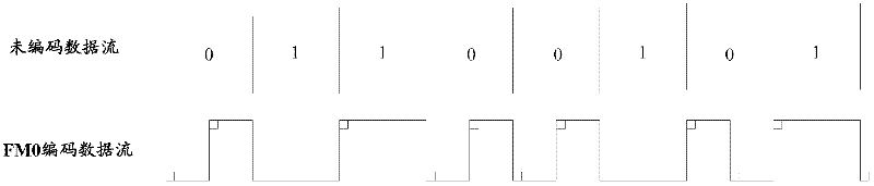
Decoding method and decoding device of FM0 coded data
A technology of encoding data and decoding method, which is applied in the field of decoding method and device of FM0 encoded data, can solve the problems of slow decoding process, inability to decode data, and low decoding rate of high-performance hardware chips, so as to reduce the frequency of data collection, The effect of reducing performance requirements and reducing resource costs
- Summary
- Abstract
- Description
- Claims
- Application Information
AI Technical Summary
Problems solved by technology
Method used
Image

Examples
Embodiment 1
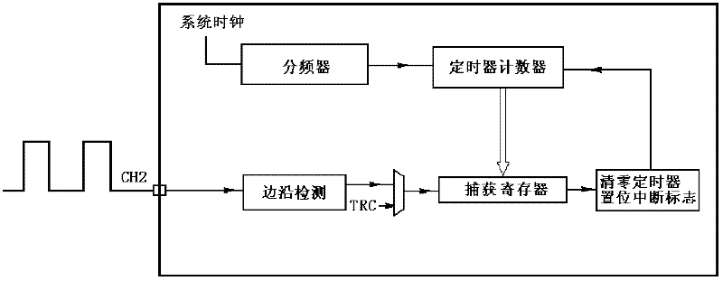
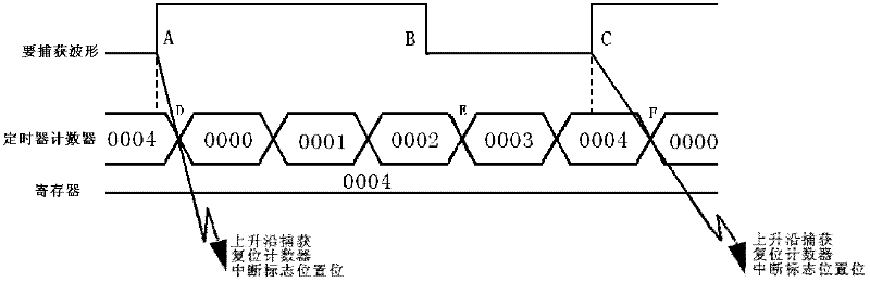
[0035] Embodiment 1. In this embodiment, the timer is in a single-register input capture mode. The single-register input capture mode is an extension of the timer function. There is only one register corresponding to the timer, and one input terminal is set as a rising edge or falling edge detection port. Such as figure 2 The input capture hardware shown, the timer corresponds to the capture register. In this way, the external waveform enters the MCU through CH2 and is internally linked to the edge detector. When CH2 detects the corresponding edge, the value of the timer is automatically saved to the capture register, and the interrupt flag is set, and the timer is cleared on the subsequent edge of the timer. If the timer interrupt is enabled, it will immediately enter the interrupt function for processing.
[0036] In the single-register input capture mode, the rising edge is valid or the falling edge is valid is obtained by configuring the MCU. Therefore, before decoding...
Embodiment 2
[0076] Embodiment 2. In this embodiment, the timer is in a PWM (Pulse Width Modulation, pulse width modulation) input capture mode.
[0077] The PWM input capture mode of the MCU is an extension of different input captures of the timer. The same input terminal is mapped to the two transition edge detection ports of the timer, that is, the timer corresponds to two registers. Such as Figure 7 As shown in the PWM input capture hardware, the external waveform enters the MCU through CH2, and is internally linked to the transition edge detectors of CH1 and CH2. The polarity of the jump edge detectors of CH1 and CH2 is opposite. When the jump edge detector of CH1 detects the corresponding jump edge, the value of the timer is automatically saved in the CC1 register; when CH2 detects the corresponding jump edge, Save the value of the timer to the CC2 register automatically, and set the interrupt flag bit, and clear the timer on the subsequent timer jump edge. If the timer interrupt ...
PUM
 Abstract
Description
Claims
Application Information