Automatic stem pulling device

A rod pulling machine and automatic technology, applied in the fields of harvesters, agricultural machinery and implements, applications, etc., can solve the problems of wasting manpower, time-consuming and laborious, troublesome operation, etc., and achieve the effect of reducing labor intensity, convenient use and simple operation.

Inactive Publication Date: 2012-07-04
NANJING VOCATIONAL UNIV OF IND TECH
View PDF6 Cites 9 Cited by
  • Summary
  • Abstract
  • Description
  • Claims
  • Application Information

AI Technical Summary

Problems solved by technology

At present, the method of manual cutting or manual pulling is generally used, such as cutting off the rod, or manually pulling out the rod, which is not easy to operate and takes time and effort, resulting in the difficulty of completely pulling out the stem and wasting labor.
Pulling out the plant stems by using this traditional manual cutting or manual pulling method not only causes the stems to be easily broken, but also difficult to uproot, resulting in low work efficiency, waste of manpower and financial resources
However, the mechanized cutting method has high cutting cost and is not easy to operate and has poor flexibility.
The rapid economic and social development has brought significant changes to people's lives, but with the increase in the demand for stem plants, the workload of pulling out stem plants has become larger. Difficulties in reusing land can no longer meet current needs

Method used


Image

  • Automatic stem pulling device
  • Automatic stem pulling device
  • Automatic stem pulling device

Examples


Embodiment Construction

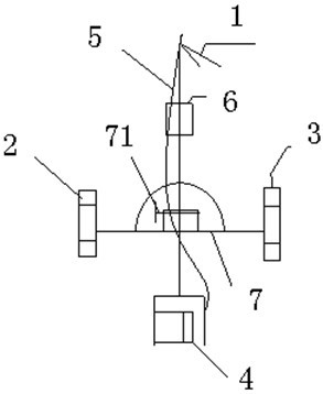
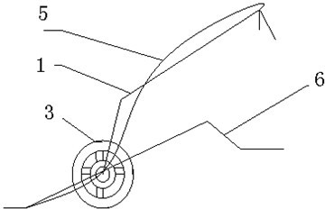
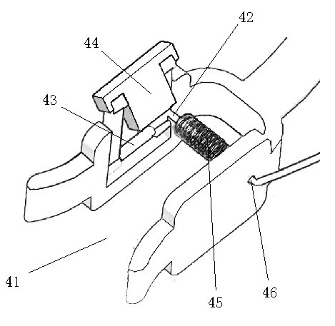
[0013] A kind of automatic rod puller device of the present invention, see figure 1 and figure 2 , the device comprises a handle 1, a left wheel 2, a right wheel 3, a clamping device 4, a hand brake system 5 and a pedal 6, and the left wheel 2 and the right wheel 3 are respectively arranged at two ends of a connecting shaft 7. The handle 1 is Y-shaped, and the split part at the front end is arranged on the connecting shaft 7 . Pedal 6 is as a lever structure form, and the middle part of pedal 6 is arranged on the connecting shaft 7 by rotating shaft 71. The clamping device 4 is arranged at the front end of the pedal 6 and is located at the front side of the connecting shaft 7 . image 3 It is a structural schematic diagram of the clamping device in the present invention. The clamping device 4 includes a U-shaped groove 41, a connecting rod 42, a connecting rod shaft 43, a clamp block 44 and a spring 45, and the clamp block 44 is arranged in the U-shaped groove through the c...


PUM


Abstract

The invention discloses an automatic stem pulling device. The device comprises a handle, a left wheel, a right wheel, a clamping device, a handbrake system and a pedal, wherein the left wheel and the right wheel are respectively arranged at the two ends of a connecting shaft; the front end of the handle is arranged on the connecting shaft; the middle part of the pedal is arranged on the connecting shaft via a rotating shaft; the clamping device is arranged at the front end of the pedal and positioned on the front side of the connecting shaft; and the handbrake system is arranged at the rear end of the handle, used for shrinking the opening of the clamping device and connected with the clamping device. The device can automatically remove plant stems, is simple in structure and strong in flexibility, is simple to operate and easy to carry, is suitable for various environments and has the advantages of high stem removal efficiency and high cost performance.

Description

Technical field [0001] The present invention involves a mechanical device, which specifically speaking a automatic pull -up machine device for pulling out plant rods. Background technique [0002] As the pace of life accelerates now, plant rods have become time -consuming and labor -consuming physical labor, and the planting of rod plants occupies a large proportion of all plants.At present, hand -cutting or hand -lifting methods are generally used, such as cutting rods, or manual pulling rods and other devices. It is not easy to operate and takes time and effort, resulting in the difficulty of thoroughly pulling out the rod stems, and wasted the labor force.The traditional hand -cutting or hand -lifting method is used to pull out the plant rods not only caused the pole to break, but it is difficult to connect to the uproot. The work efficiency is low, and the manpower and financial resources.The mechanized cutting method is high and difficult to operate, and the flexibility is p...

Claims


Application Information

Patent Timeline
Patent Type & Authority Applications(China)
IPC IPC(8): A01D45/00
Inventor 耿昌徐元潮施玲杰张云玲黄杰
Owner NANJING VOCATIONAL UNIV OF IND TECH
Why Eureka
Try Eureka