
Dust removal device and method for manufacturing same

A technology of a dust removal device and a manufacturing method, which are applied in the directions of cleaning methods, cleaning methods and utensils, chemical instruments and methods using gas flow, etc., can solve the problems of difficulty in controlling the ejection amount and can only be erected and ejected, and achieve a simple and easy-to-achieve effects

Inactive Publication Date: 2012-07-04
广东好顺欧迪斯科技股份有限公司
View PDF6 Cites 0 Cited by
  • Summary
  • Abstract
  • Description
  • Claims
  • Application Information

AI Technical Summary

Problems solved by technology

However, the existing aerosol bottles still have many disadvantages, such as spraying only upright, difficulty in controlling the amount of spraying, etc.

Method used


Image

  • Dust removal device and method for manufacturing same
  • Dust removal device and method for manufacturing same
  • Dust removal device and method for manufacturing same

Examples


Embodiment Construction

[0028] In order to describe the technical content, structural features, achieved goals and effects of the present invention in detail, the following will be described in detail in conjunction with the embodiments and accompanying drawings.

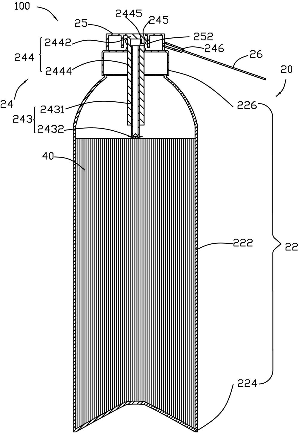
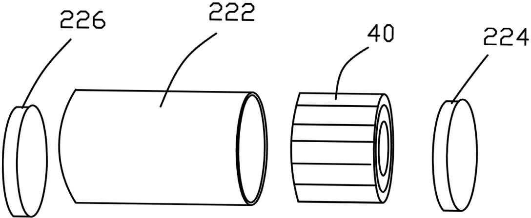
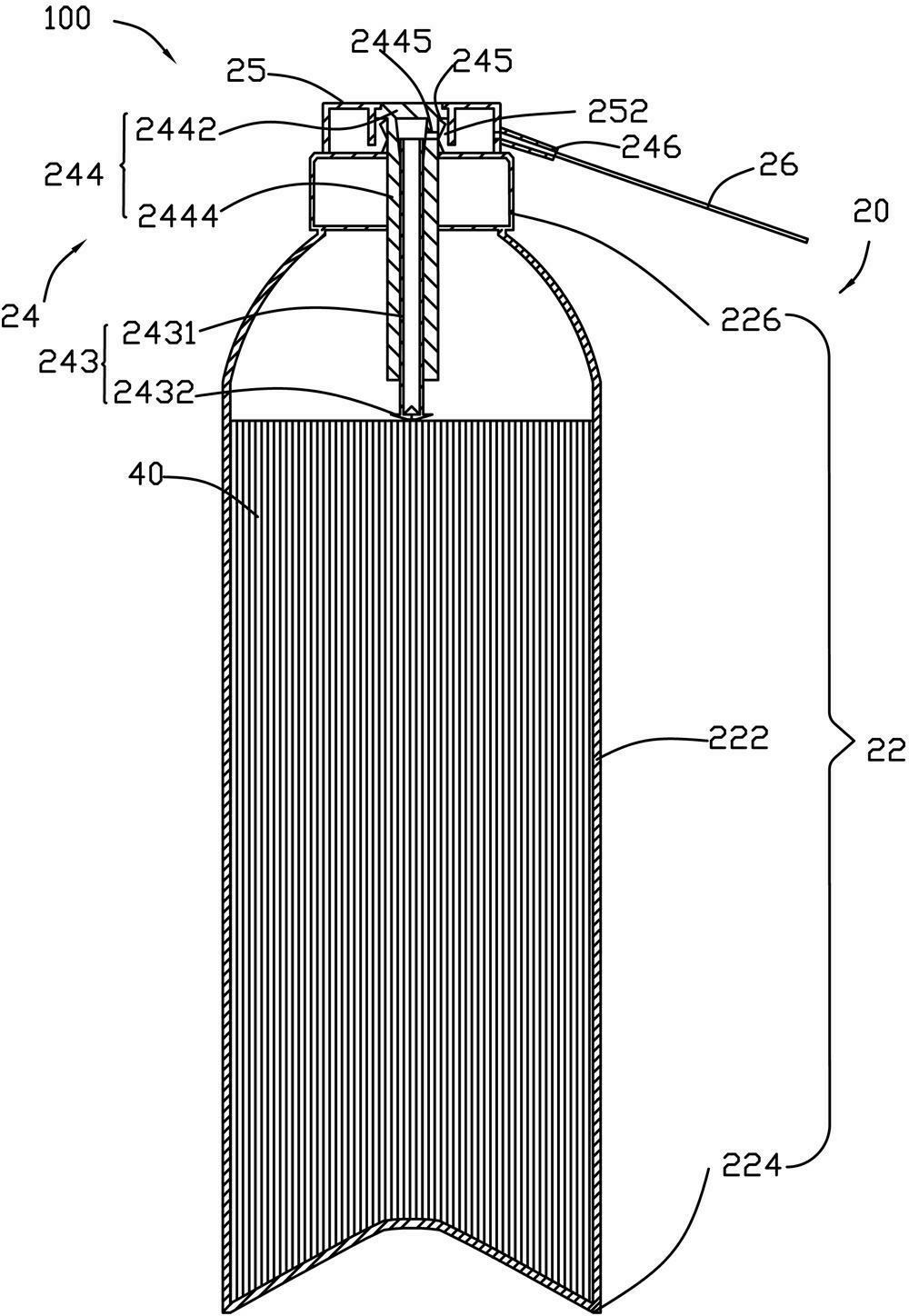
[0029] The dust removal device of the present invention can be used for blowing the dust on the object, especially for blowing the dust in the narrow gaps and holes of the object.

[0030] see figure 1 , the dust removal device 100 of the first preferred embodiment of the present invention is used for blowing dust. The dust removal device 100 includes an aerosol can 20 , and a propellant (not shown in the figure) and an adsorbent 40 assembled in the aerosol can 20 . The aerosol can 20 includes a can body 22 , a valve body 24 , a gland 25 and a conduit 26 . The tank body 22 can be made of multiple metal sheets, such as iron sheets, aluminum sheets and the like. The tank body 22 includes a cylinder body 222 , a tank bottom 224 and a tank ...


PUM


Abstract

The invention relates to a dust removal device and a method for manufacturing the same. The dust removal device comprises an aerosol tank, the aerosol tank comprises a cylinder and a valve, the valve is arranged on the cylinder, propellants and adsorption materials are filled in the cylinder, and the adsorption materials include one or a few of nonwoven fabrics, fluff pulp, wood pulp cotton, broken cotton velvet, cotton gauzes, toilet paper, cotton rags, vermiculite powder and expanded perlite powder. The adsorption materials adsorb all or most of the propellants, liquid propellants cannot flow out and can be sprayed in any directions, and the spray quantity can be effectively controlled. Besides, the method for manufacturing the dust removal device is simple and is easy to implement.

Description

[0001] technical field [0002] The invention relates to a dust removal device and a manufacturing method of the device, in particular to a dust removal device for blowing dust in narrow gaps and holes and a manufacturing method of the device. [0003] Background technique [0004] In order to improve the yield of precision substrates such as printed circuit substrates and liquid crystal substrates, it is necessary to remove the dust attached to the workpiece as much as possible before performing precision operations such as firing circuit diagrams and assembling, especially in some narrow areas, such as precision instruments, circuits, etc. The narrow gap and hole of the board. Existing is usually removed by sweeping or spraying. Wherein, the spray method is to fill the aerosol bottle with liquefied gas, and the dust will be blown off when the liquefied gas is sprayed out. However, the existing aerosol bottle also has many disadvantages, such as the spraying can only be ...

Claims


Application Information

Patent Timeline
IPC IPC(8): B08B5/02
Inventor 黄超家新发
Owner 广东好顺欧迪斯科技股份有限公司
Learn More