
Three-degree-of-freedom parallel-connection mechanical wrist

A degree of freedom and parallel technology, applied in the field of mechanical wrists, can solve the problems of heavy weight and large moment of inertia of mechanical wrists, and achieve the effect of simple and compact structure, high degree of modularization, and error compensation

Active Publication Date: 2012-07-04
秦皇岛燕盛智能科技有限公司
View PDF9 Cites 28 Cited by
  • Summary
  • Abstract
  • Description
  • Claims
  • Application Information

AI Technical Summary

Problems solved by technology

The mechanical wrist installed at the end of the traditional mechanical arm is a series mechanism, and its driving motor is generally located near the rotating pair, resulting in heavy weight and large motion inertia of each component of the mechanical wrist

Method used


Image

  • Three-degree-of-freedom parallel-connection mechanical wrist
  • Three-degree-of-freedom parallel-connection mechanical wrist
  • Three-degree-of-freedom parallel-connection mechanical wrist

Examples


Embodiment 1

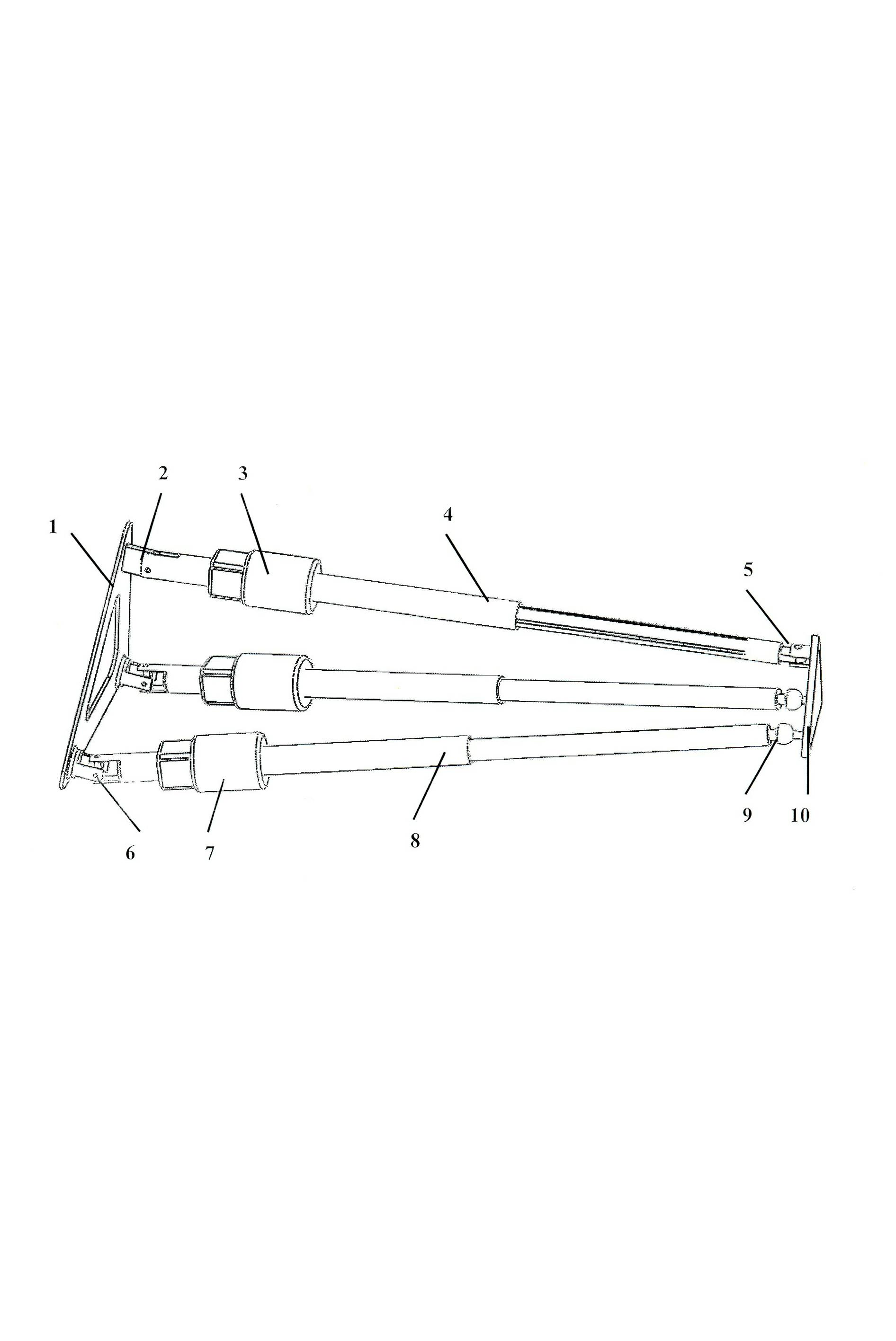
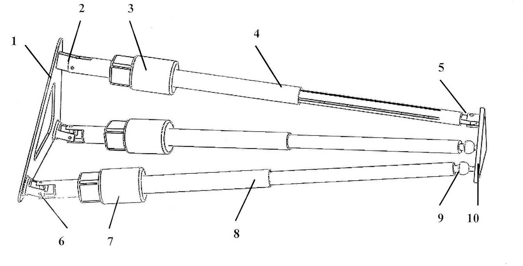
[0017] exist figure 1 In the three-dimensional schematic diagram of a 3-DOF parallel mechanical wrist shown, the two ends of a constrained driving branch chain and two driving branch chains with the same structure are respectively connected to the machine base 1 and the moving platform 10, and the connection points are all in the shape of an equilateral triangle Symmetrically distributed, the driving motors 3 and 7 of each branch chain are all installed on the mobile pair near the side of the machine base. The constraining driving branch chain is an RPR type series structure, in which one end of the driving moving pair 4 is connected to the machine base through the rotating pair 2 , and the other end of the driving moving pair is connected to the moving platform through the rotating pair 5 . The axes of the above two revolving pairs are respectively parallel to the planes of the machine base and the moving platform. When the rotation angles of the above two revolving pairs are...

Embodiment 2

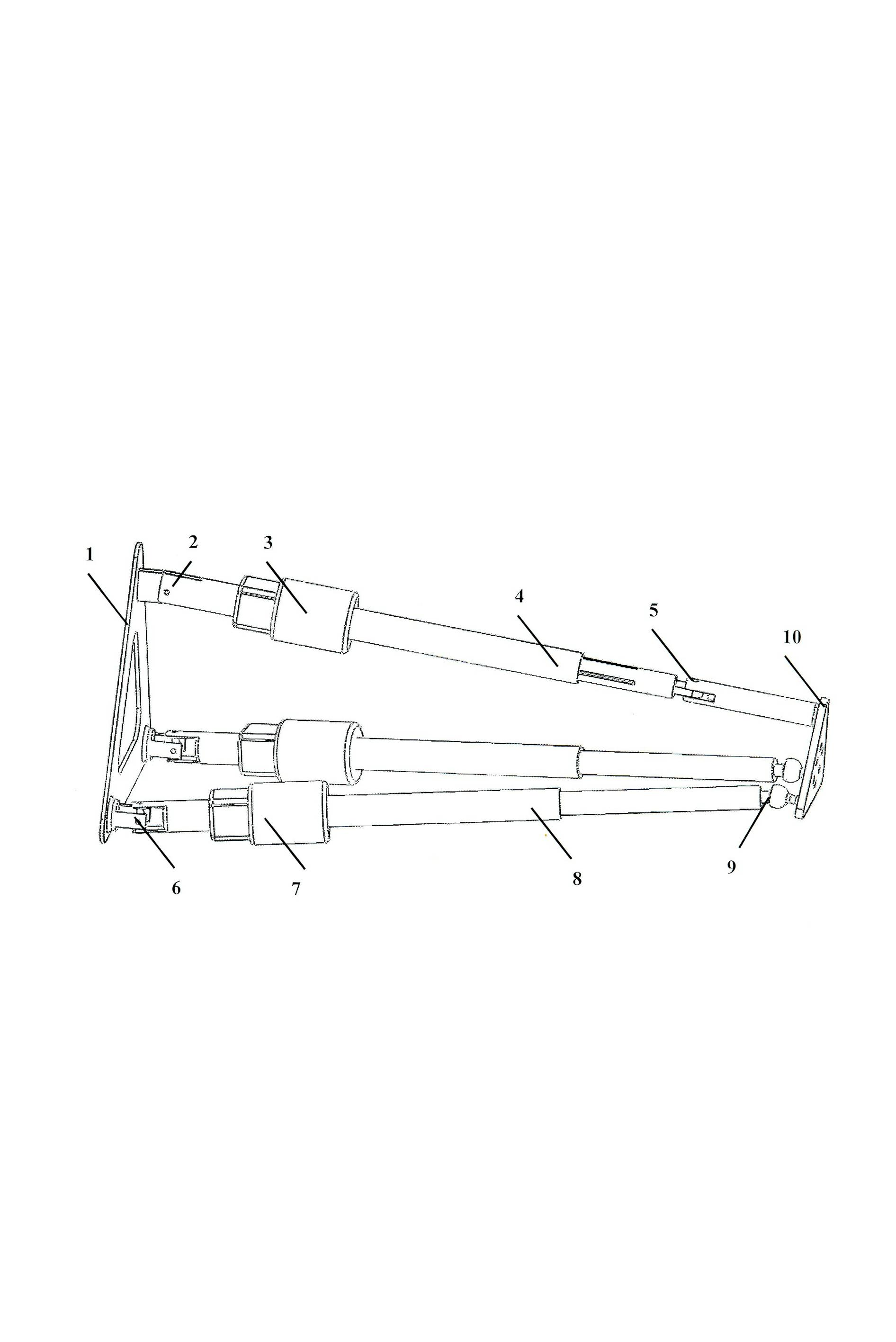
[0019] exist figure 2 In the three-dimensional schematic diagram of a parallel mechanical wrist with 3 degrees of freedom shown, the length between the center line of rotation of the revolving pair 5 and the moving platform 10 in the constraining drive branch chain is increased, and other components and their connection relationship are the same as figure 1 same.


PUM


Abstract

The invention relates to a three-degree-of-freedom parallel-connection mechanical wrist which comprises a base, a movable platform, a constrain driving branch chain used for connecting the base with the movable platform, and two driving branch chains which are same in structure, wherein the two ends of the three branch chains are symmetrically distributed in a regular triangle shape together with the base and the movable platform; the constrain driving branch chain consists of two revolute pairs and a driving sliding pair, so that a resilient packet ring (RPR)-type series-connection structural branch chain can be formed; the constrain driving branch chain is connected with the base and the movable platform by virtue of the revolute pairs; the two driving branch chains which are completely the same as each other respectively comprise a universal pair, a movable driving pair and a spherical hinge, so that an uninterrupted power supply (UPS)-type series-connection structural branch chain can be formed; and the two driving branch chains are respectively connected with the base by virtue of the universal pairs, and connected with the movable platform by virtue of the spherical hinges. The three-freedom parallel-connection mechanical wrist has the advantages of being strong in carrying capacity, good in stability, large in work space, high in flexibility, simple in structure, fewer in moving branch chains, hard to interfere, free from self micro-movement, high in accuracy, easy to control since a driver is close to the base, etc.

Description

technical field [0001] The invention relates to a mechanical wrist, in particular to a parallel mechanical wrist. Background technique [0002] There are few research results on the use of parallel mechanisms as mechanical wrists, and the current mechanical wrists basically use series mechanisms. Chinese patent CN201010161423.3 discloses a mechanical wrist with an anti-jamming mechanism, which is mainly characterized in that the anti-jamming function is realized through a combination of bearings. Chinese patent CN201020698026.5 discloses a series structure explosion-proof heavy-duty mechanical wrist, which is mainly characterized in that it is flame-proof and capable of heavy load. Chinese patent CN200810083584.8 discloses an articulated mechanical wrist, which is mainly characterized in that a series mechanism is used to form a joint to realize the function of the wrist. Chinese patent CN200510136710.8 discloses a mechanical wrist suitable for underwater work, and its mai...

Claims


Application Information

Patent Timeline
IPC IPC(8): B25J17/00
Inventor 张典范荣誉金振林
Owner 秦皇岛燕盛智能科技有限公司
Learn More