Pipe reeling machine

A tube reeling machine and tube reeling technology, which is applied in the directions of coiling strips, thin material processing, transportation and packaging, can solve the problems of complicated structure, high labor intensity and low efficiency of the tube reeling machine, and achieves simple structure and low energy consumption. The effect of labor intensity and convenient operation

Active Publication Date: 2014-11-26
ZHUHAI PAINTER TECH
View PDF9 Cites 0 Cited by
  • Summary
  • Abstract
  • Description
  • Claims
  • Application Information

AI Technical Summary

Problems solved by technology

The structure of the currently used pipe reels is relatively simple, and they are all operated manually, which is labor-intensive and inefficient; while the structure of the pipe reels with a high degree of automation is very complicated, and the operation is relatively cumbersome.

Method used


Image

  • Pipe reeling machine
  • Pipe reeling machine

Examples


Embodiment Construction

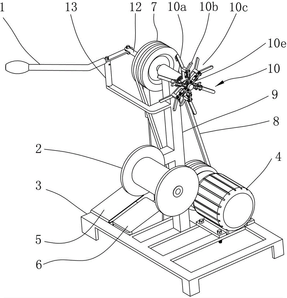
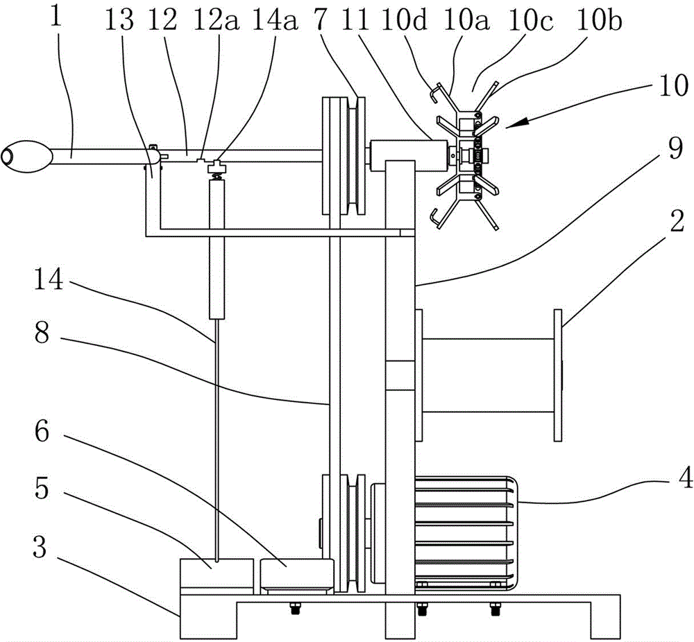
[0018] as attached figure 1 , attached figure 2 A hose reel shown includes a base 3, a bracket 9 mounted on the base 3, and a tube reel mechanism mounted on the bracket 9, and the reel mechanism is provided with a gripper 10 that can be opened and closed to curl the pipe And drive the driven wheel 7 that grabs 10 rotations, is provided with bearing seat 11 between described driven wheel 7 and grabs 10 and is connected; Described support 9 is provided with charging roller 2. Described driven wheel 7 is provided with belt 8 and is connected with a motor 4, and motor 4 drives driven wheel 7 to rotate, thereby makes driven wheel 7 drive catch disc 10 to rotate. The base 3 is provided with a foot switch 6 that can turn on the motor 4, which is convenient for the operator to operate and can start or stop the machine at any time.

[0019] As a preferred embodiment of the present invention, a gripper drive mechanism is also installed on the bracket 9, and the gripper drive mechanis...


PUM


Abstract

The invention discloses a pipe reeling machine which comprises a pedestal, a support mounted on the pedestal and a pipe reeling mechanism mounted on the support, wherein the pipe reeling mechanism is provided with a grasping plate which can be opened or closed and reels a pipe, and a driven wheel which drives the grasping plate to rotate; a bearing support is arranged between the driven wheel and the grasping plate and used for connecting the driven wheel and the grasping plate; a grasping plate driving mechanism is further mounted on the support, and comprises a grasping plate driving rod which can move axially to open or close the grasping plate; the grasping plate driving rod is mounted inside the bearing support; the end part of the grasping plate driving rod is movably connected with the grasping plate; and a grasping plate driving rod positioning mechanism is arranged on the pedestal. The pipe reeling machine has a simple structure, is convenient to operate, effectively reduces the labor intensity of workers and increases the production efficiency. Besides, the pipe reeling machine can control the inside diameter, the outside diameter and the horizontal height of a pipe which is reeled.

Description

technical field [0001] The invention relates to a pipe coiling machine, which is used for coiling fixed-length pipes, and can fix the inner diameter, outer diameter and laying height within a certain range after curling. Background technique [0002] Hose coiling machine is widely used in all walks of life. It can curl various long strip products for easy handling and storage. The relatively simple structure of the coiling machines currently in use is operated purely by hand, which is labor-intensive and inefficient; while the structure of the coiling machines with a high degree of automation is very complicated and the operation is relatively cumbersome. Contents of the invention [0003] In order to solve the above problems, the present invention provides a coiler with simple structure and convenient operation. [0004] The technical scheme that the present invention adopts for solving its problem is: [0005] A hose coiling machine, comprising a base, a bracket mounte...

Claims


Application Information

Patent Timeline
Patent Type & Authority Patents(China)
IPC IPC(8): B65H18/10
Inventor 陈宇
Owner ZHUHAI PAINTER TECH
Why Eureka
Try Eureka