Laundry dryer with variable dry air volume flow and method for operating same

A technology of drying machine and drying air, applied in the field of drying machine

Inactive Publication Date: 2012-07-04
V ZUG
View PDF0 Cites 9 Cited by
  • Summary
  • Abstract
  • Description
  • Claims
  • Application Information

AI Technical Summary

Problems solved by technology

Both airflows ...

Method used


Image

  • Laundry dryer with variable dry air volume flow and method for operating same
  • Laundry dryer with variable dry air volume flow and method for operating same

Examples


Embodiment Construction

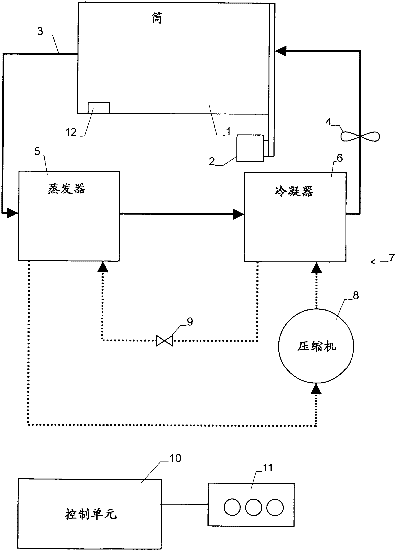
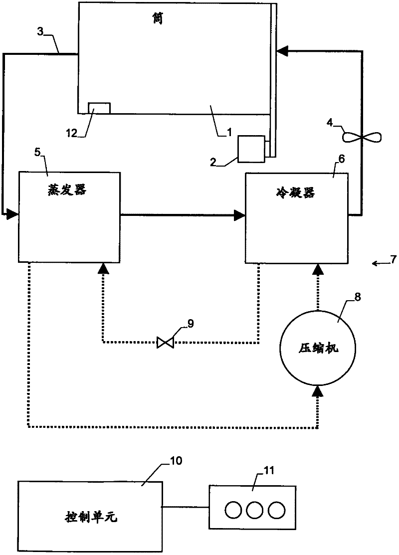
[0015] The clothes dryer according to the attached figures comprises a tub 1 for receiving laundry to be dried. The drum 1 is advantageously rotated by means of a transmission 2 with a reversing movement, ie the direction of rotation changes with a reversing rhythm to reduce the tendency of the laundry to become tangled.

[0016] The cartridge 1 is arranged in a drying air circuit 3 . In the present embodiment the air circuit is a closed air circuit, although in principle the invention can also be used with an open air flow in which part of the dry air is replaced at least every once in a while by fresh air.

[0017] A fan 4 is provided for conveying air through the drying air circuit 3 . From the ventilator 4 the drying air reaches the drum 1 and from there the drying air passes through the evaporator 5 and the condenser 6 of the heat pump 7 and finally returns to the ventilator 4 .

[0018] The heat pump 7 comprises a compressor 8 which pumps the heat pump fluid in a known...


PUM


Abstract

The invention relates to a laundry dryer. Air flow of the drying air in the laundry dryer can be varied. In particular, the air flow can be reduced as the drying process proceeds, such that the air has enough time to take up a large amount of water from the laundry and it remains possible to extract water therefrom efficiently. Further, the user can be provided with different programs having different air flows and process durations such that the duration, energy consump tion and noise generation can be chosen according to re quirements. Advantageously, the power of a heat pump (7) in the device can be adjusted depending on air flow.

Description

technical field [0001] The invention relates to a clothes dryer having a drying air circuit, a drum arranged in the air drying circuit for receiving laundry to be dried, a fan for generating an airflow of drying air in the drying air circuit , and a control unit for controlling the ventilator. Furthermore, the invention relates to a method for operating the dryer. Background technique [0002] In known clothes dryers the drying air in the air circuit is conveyed through a drum which allows the laundry to be dried to be dried. While high airflow helps improve drying efficiency, it increases energy consumption and noise. Contents of the invention [0003] The problem to be solved by the present invention is to provide improved airflow control for a clothes dryer and method of operation thereof. This object is achieved by the independent claims. [0004] Therefore, the control unit of the clothes dryer is adapted to generate at least two different airflows in the drying a...

Claims


Application Information

Patent Timeline
IPC IPC(8): D06F58/02D06F58/20D06F58/26D06F58/28D06F58/48D06F58/52
CPCD06F58/206D06F2058/2864D06F58/28D06F2103/36D06F2105/24D06F2101/20D06F2105/26D06F58/52D06F58/48D06F2105/48D06F2103/34D06F2103/08Y02B40/00
Inventor M·克什多费尔A·维德莫
Owner V ZUG
Why Eureka
Try Eureka