Supercharge Your Innovation With Domain-Expert AI Agents!

Shell oil distribution type cylindrical blade hydraulic pump

A technology of hydraulic pump and vane, applied in the field of shell-distributed cylindrical vane hydraulic pump, can solve the problems of fast wear, low output pressure and poor sealing performance of the hydraulic pump, and achieve the effects of easy processing, high pressure and long service life

Inactive Publication Date: 2012-07-04
ZHEJIANG UNIV
View PDF8 Cites 6 Cited by
  • Summary
  • Abstract
  • Description
  • Claims
  • Application Information

AI Technical Summary

Problems solved by technology

This type of vane pump is sealed by a contact line between the vane and the cylinder body, so the sealing performance is poor, and the output pressure is low. In addition, there is a lot of friction between the vane, the rotor and the cylinder body during rotation, resulting in the hydraulic pump as a whole. Fast wear, short life, low efficiency

Method used


Image

  • Shell oil distribution type cylindrical blade hydraulic pump
  • Shell oil distribution type cylindrical blade hydraulic pump
  • Shell oil distribution type cylindrical blade hydraulic pump

Examples


Embodiment Construction

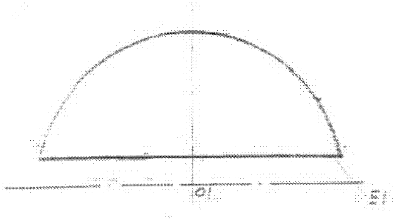
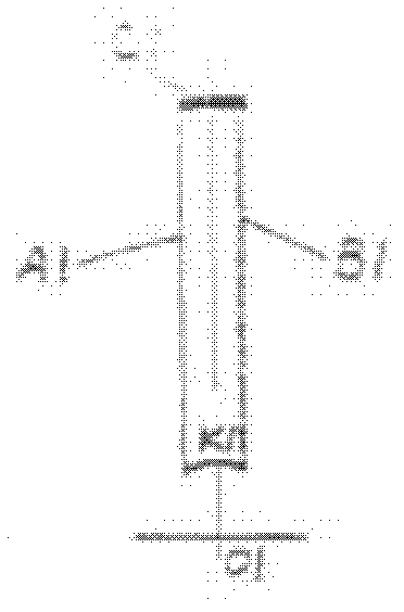
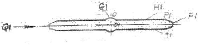
[0036] Such as Figure 13 As shown, the shell oil-distributed cylindrical vane hydraulic pump of the present invention includes a housing 1 , a rotor 2 , two vanes 3 , two sealing strips 4 and two pads 5 . The rotor 2 is located in the center, the housing 1 is located outside, and the two blades 3 are respectively located on both sides of the rotor 2, and are placed in the hollow ring (that is, the guide groove) at the opposite corner of the housing 1, forming an angle with the rotor 2, The tangent of the angle is the ratio of the height of the housing 1 to the diameter of the bottom circle of the housing 1 . A plane of the blade 3 is tangent to the side of the circular table of the rotor 2, and the sealing strip 4 is located between the rotor 2 and the blade 3, and one side of the plane is attached to a plane of the rotor 2, and the cylindrical side is connected to the cylindrical surface of the blade 3 The E1 fits together, and the spacer 5 is located in the hollow ring at ...


PUM


Abstract

The invention discloses a shell oil distribution type cylindrical blade hydraulic pump which comprises a shell, a rotor, two blades, two sealing strips and two cushion blocks. The rotor is positioned at the center; the shell is arranged outside; the two blades are respectively positioned at both sides of the rotor and are arranged in hollow circular rings at the opposite angles of the shell; an angle is formed between each blade and the rotor; the tangent of the angle is a ratio of the height of the shell to the diameter of the bottom circumference of the shell; the sealing strips are positioned between the rotor and the blades; the plane sides of the sealing strips are attached to one planes of the rotors; the cylindrical surface sides of the sealing strips are attached to cylindrical surfaces E1 of the blades; the cushion blocks are positioned in the hollow circular rings at the opposite angles of the shell; and the vacancy formed by the blades, the rotor and the sealing strips is just full filled with the cushion blocks. According to the invention, all the sealing positions are in a face seal mode and the shell oil distribution type cylindrical blade hydraulic pump has high discharge capacity, high pressure, high efficiency, high specific power and compact structure, is relatively easy to process and has low cost and long service life.

Description

technical field [0001] The invention relates to a hydraulic pump, in particular to a shell oil distribution type cylindrical vane hydraulic pump. Background technique [0002] The structure of the existing vane hydraulic pump is that the rotor is placed eccentrically in the oil cylinder, and the vanes are placed in the rotor radially or at a certain angle with the rotor radius. When working, the rotor rotates at high speed, and the vanes are thrown out under the action of centrifugal force. The body forms a sealed cavity, and the volume change generates pressure when it rotates. This type of vane pump is sealed by a contact line between the vane and the cylinder body, so the sealing performance is poor, the output pressure is low, and there is a lot of friction between the vane, the rotor and the cylinder body during rotation, resulting in the hydraulic pump as a whole. Fast wear, short life and low efficiency. In addition, in order to ensure that the blades can safely ent...

Claims


Application Information

Patent Timeline
IPC IPC(8): F04C2/344F04C15/00
Inventor 陈行金波
Owner ZHEJIANG UNIV
Features
  • R&D
  • Intellectual Property
  • Life Sciences
  • Materials
  • Tech Scout
  • Unparalleled Data Quality
  • Higher Quality Content
  • 60% Fewer Hallucinations
Learn More