Supercharge Your Innovation With Domain-Expert AI Agents!

Gasket

A sealing ring and sealing lip technology, which is applied in the direction of engine sealing, engine components, mechanical equipment, etc., can solve problems such as sealing lip leakage and achieve high robustness

Active Publication Date: 2012-07-04
CARL FREUDENBERG KG
View PDF6 Cites 2 Cited by
  • Summary
  • Abstract
  • Description
  • Claims
  • Application Information

AI Technical Summary

Problems solved by technology

As a result, leakage may occur in the area of ​​the sealing lip

Method used


Image

  • Gasket
  • Gasket
  • Gasket

Examples


Embodiment

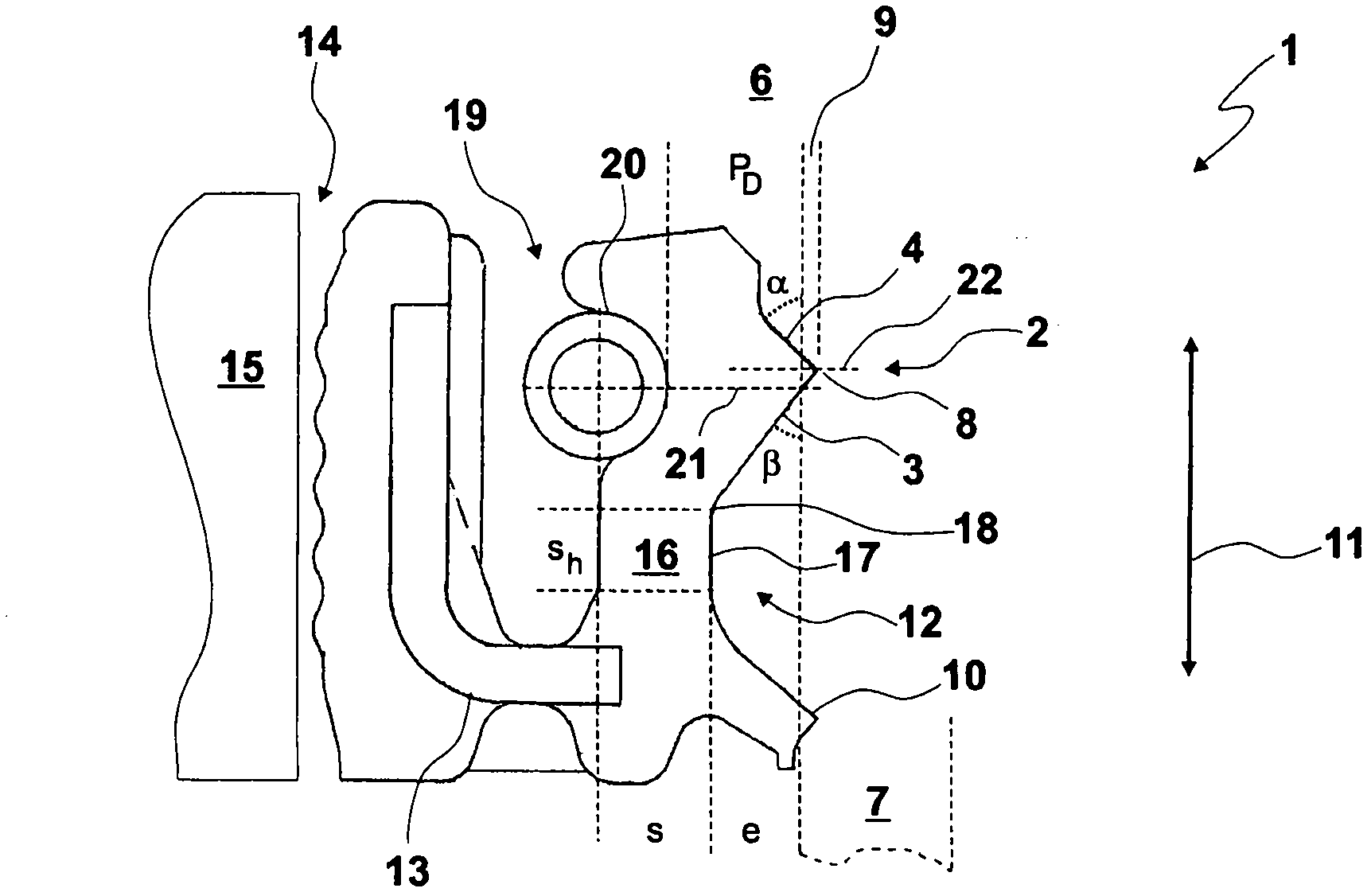
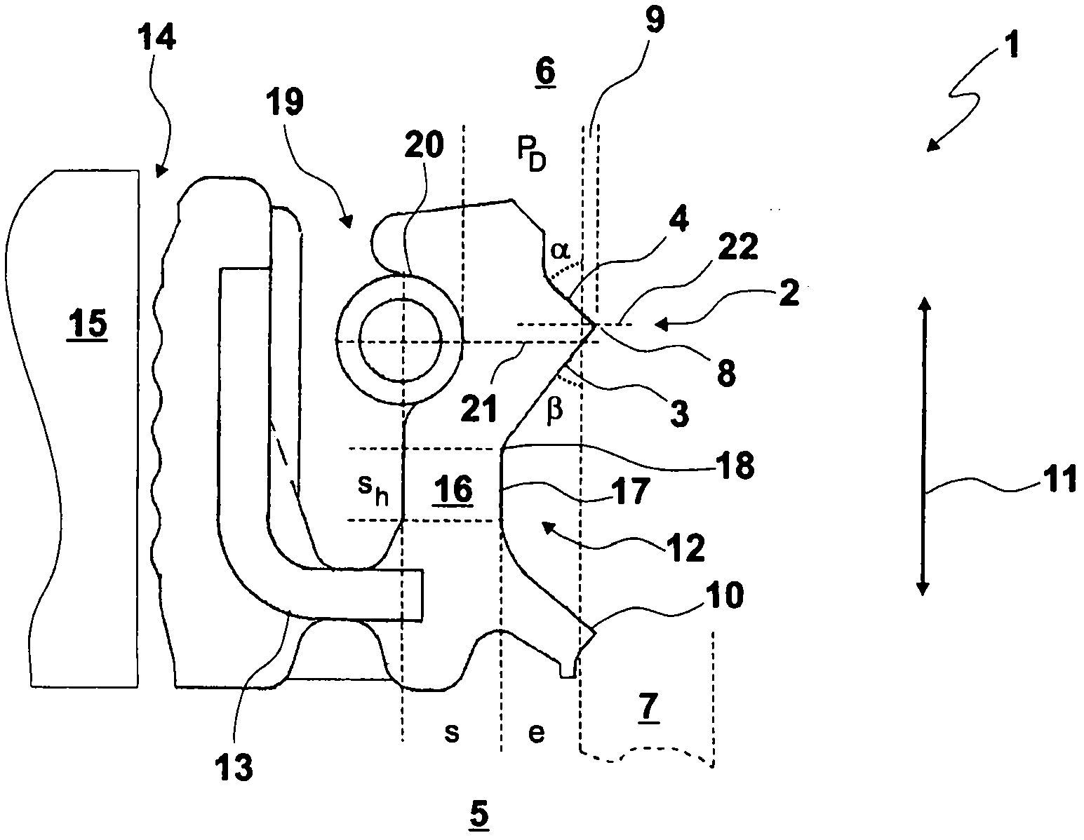
[0040] Such as figure 1 One possible embodiment shown in Dimensional Variations

[0041] parameters

Favorable value range

preferred value range

P D

0.8 to 1.6mm

1.1 to 1.3mm

s

0.6 to 1.2mm

0.8 to 1.0mm

s h

0.4 to 1.1mm

0.6 to 0.9mm

e

0.4 to 1.0mm

0.6 to 0.8mm

α

30 to 45 degrees

35 to 40 degrees

β

37 to 50 degrees

42 to 45 degrees

[0042] exist figure 1 In the embodiment shown, all combinations of the above-mentioned values ​​for the parameters are permissible and applicable.

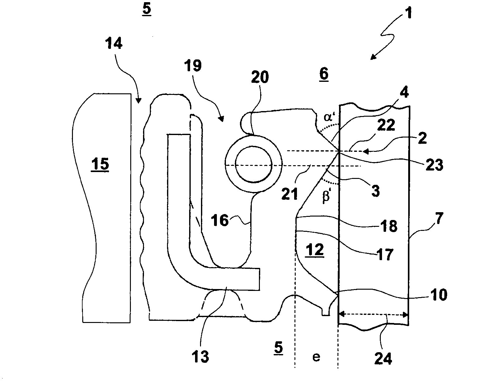
[0043] exist figure 2 is shown in the mounting position with the shaft 7 according to the figure 1 The sealing ring 1. Here, the first angle β' and the second angle α' in the installed position differ from the first angle β' and the second angle α in the unassembled state. Furthermore, a contact surface 23 is formed when the shaft 7 is mounted.

[0044] In the installed po...


PUM


Abstract

A radial shaft sealing ring for the sealing separation of an internal space (6), from an external space (5), with a sealing lip (2) delimited by a first and a second annular surface (3, 4) of a cone frustum, wherein, the first annular surface (3) is oriented towards the external space (5), and the second annular surface (4) is oriented towards the internal space (6), wherein the annular surfaces (3, 4) are connected to each other via a ring-shaped contact surface (23) of the sealing lip (2), which rests on the shaft (7), wherein the first annular surface (3) forms with the shaft (7) a first angle ([beta]') of 23-40 DEG in the installed position, wherein an inner diameter (24) of the ring-shaped contact surface (23) is 1-15 mm in the installed position.

Description

technical field [0001] The invention relates to the sealing of a housing opening passed through by a shaft by means of a sealing ring, wherein the sealing ring separates an inner space, which at least partially surrounds the shaft, from an outer space. In this case, the interior can be a housing interior, which is separated by a sealing ring in a pressure-tight manner from the outer space surrounding the housing, so that liquids, gases and / or particulate matter cannot escape from the housing. The material cannot flow out of the cavity, and the material cannot enter the inner cavity of the housing from the outer cavity. The invention therefore also relates to a housing with such a sealing ring. Background technique [0002] A sealing ring designed as a radial shaft sealing ring is known from EP 1156242 B1, which is formed from an annular, metallic support body and a sealing lip connected thereto. In the installed position, the radial shaft sealing ring is passed through by ...

Claims


Application Information

Patent Timeline
IPC IPC(8): F16J15/32
CPCF16J15/3212
Inventor R·德鲁克滕亨斯特U·埃平
Owner CARL FREUDENBERG KG
Features
  • R&D
  • Intellectual Property
  • Life Sciences
  • Materials
  • Tech Scout
  • Unparalleled Data Quality
  • Higher Quality Content
  • 60% Fewer Hallucinations
Learn More