Electromagnetic valve with differential pressure resistance valve core
What is Al technical title?
Al technical title is built by PatSnap Al team. It summarizes the technical point description of the patent document.
A technology of valve core and valve core seat, which is applied in the direction of valve operation/release device, valve detail, valve device, etc., which can solve the problem of pressure difference, increase of valve opening load, and leakage between the through hole of the separation layer and the meshing surface of the valve core And other issues
Active Publication Date: 2013-12-04
ZHEJIANG HENGSEN IND GROUP
View PDF5 Cites 1 Cited by
Summary
Abstract
Description
Claims
Application Information
AI Technical Summary
This helps you quickly interpret patents by identifying the three key elements:
Problems solved by technology
Method used
Benefits of technology
Problems solved by technology
However, due to the large pressure difference between the two chambers of the separation layer in the valve body, if the direction of water flow is set to be consistent with the opening direction of the valve core, the locking condition of the valve will be very poor, which will easily cause the gap between the through hole of the separation layer and the meshing surface of the valve core. Leakage; if the valve core is set to open against the direction of water flow, although the sealing performance of the valve can be improved, the load to open the valve will increase
Method used
Image
Click on the blue label to locate the original text in one second.
Reading with bidirectional positioning of images and text.
Examples
Embodiment Construction
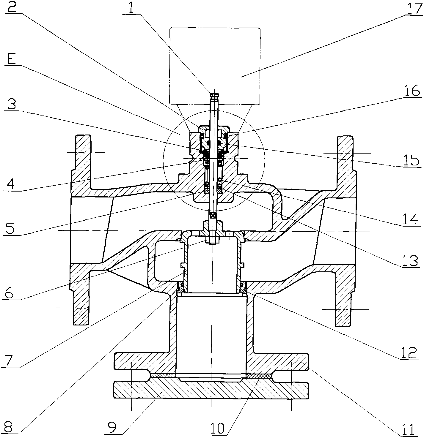
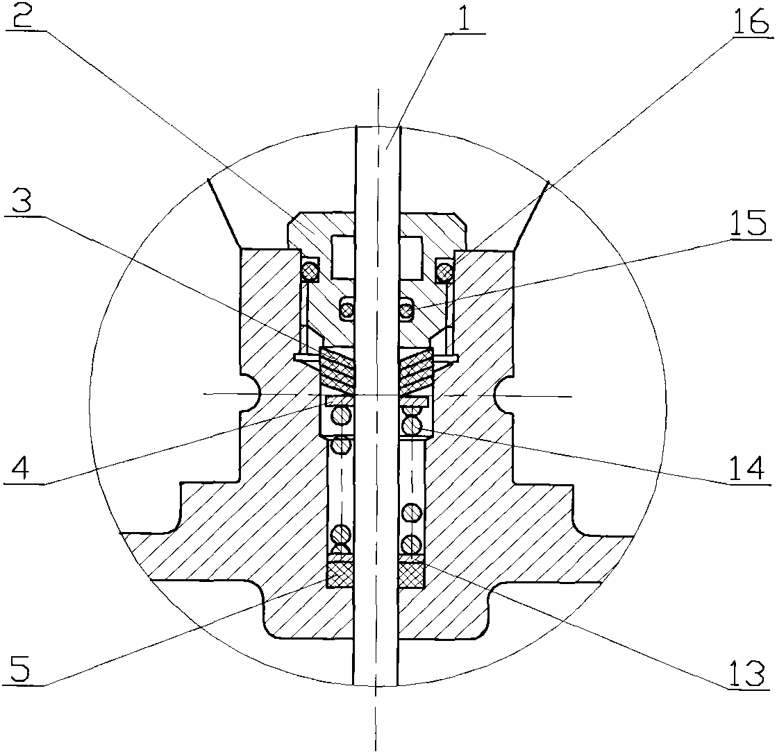
[0007] The valve body (11) is generally a T-shaped three-way structure formed by the straight-through pipe and the branch pipe intersecting. The three ports are equipped with flanges. The two ports of the valve body straight-through pipe have the same diameter. It is a plane passing through the axis, which is perpendicular to the axis of the branch pipe. On the plane, there is a round hole centered on the axis of the branch pipe. Seal washer (10) with stuffy cover (9) sealing behind. A spool seat (12) for guiding the movement of the spool (7) is provided at the junction of the inner chamber of the branch pipe and the straight-through pipe to ensure correct positioning of the spool (7) when moving up and down. A large O-ring (8) is provided at the inner groove of the spool seat (12) to make the spool (7) and the spool seat (12) seal well; above the round hole, that is, extending upward along the axis of the branch pipe port to the straight-through The pipe wall is provided wit...
PUM
Abstract
An electromagnetic valve with a differential pressure resistance valve core is composed of a valve rod, a press cap, a V-shaped sealing ring, a gasket, a sealing pad, a nut, a valve core, a large O-shaped ring, a stifle, a sealing gasket, a valve body, a valve core seat, a small sealing ring, a spring, a small O-shaped ring, a middle O-shaped ring and an electromagnet. The valve core is in a thin-wall cylindrical shape, one end of the valve core is open, the other end is provided with an end face plate, a step connected with the valve rod is positioned in the center of the end face plate, and through holes are arranged on the periphery of the step. A blocking shoulder is arranged at the periphery of the valve core to limit journey of the valve core to improve sealing performance. Under the action of the electromagnet, an upward-moving valve on the valve core is in a close state, pressure water is filled with the valve core and a cavity communicated with the valve core, the sum of axial force stressed on the valve core is nearly zero, pressure difference inside and outside the cylinder wall of the valve core is large, axial force stressed on in the cylinder wall is enough to enable the thin wall of the valve core to expand and deform, and sealing between the valve core and the valve is reliable. When the valve core moves downwards, the valve is open, and water pressure has no side effects on the valve core.
Description
technical field [0001] The invention relates to a solenoid valve with an anti-pressure difference interference spool. Background technique [0002] Solenoid valve is a type of electric valve. It uses the magnetic field generated by the electromagnetic coil to pull the valve core, thereby changing the on-off of the valve body. When the coil is powered off, the valve core will return by the pressure of the spring. Usually the valve core in the valve body adopts a piston-type structure, that is, the circular valve core is fixed on the head of the valve stem, and the end face of the valve core coincides with the through hole of the separation layer in the valve body. Control the on-off of the valve. However, due to the large pressure difference between the two chambers of the separation layer in the valve body, if the direction of water flow is set to be consistent with the opening direction of the valve core, the locking condition of the valve will be very poor, which will eas...
Claims
Application Information
Patent Timeline
Application Date:The date an application was filed.
Publication Date:The date a patent or application was officially published.
First Publication Date:The earliest publication date of a patent with the same application number.
Issue Date:Publication date of the patent grant document.
PCT Entry Date:The Entry date of PCT National Phase.
Estimated Expiry Date:The statutory expiry date of a patent right according to the Patent Law, and it is the longest term of protection that the patent right can achieve without the termination of the patent right due to other reasons(Term extension factor has been taken into account ).
Invalid Date:Actual expiry date is based on effective date or publication date of legal transaction data of invalid patent.