Displacement detection system with twist error correcting function

A technology of displacement detection and function, which is applied in the field of displacement detection system with the function of correcting torsion error, can solve the problem that the measurement accuracy of the measuring instrument cannot be fully utilized, so as to improve the reading stability and self-test ability, and reduce the torsion effect of error

Inactive Publication Date: 2012-07-04
CHANGCHUN INST OF OPTICS FINE MECHANICS & PHYSICS CHINESE ACAD OF SCI
View PDF2 Cites 7 Cited by
  • Summary
  • Abstract
  • Description
  • Claims
  • Application Information

AI Technical Summary

Problems solved by technology

[0004] In order to solve the existing displacement measurement technology, the present invention is mainly designed for the measurement accuracy of the measuring instrument itself. Although it can achieve high measurement accuracy, due to the mechanical structure accuracy or installation accuracy of the machine tool itself, the measuring instrument itself cannot The measurement accuracy cannot be fully utilized. In order to improve the stability of the system displacement measurement on the basis of the accuracy of the existing machine tool design, minimize the deviation caused by the non-linearity of the orbital motion, and reduce the requirements for installation accuracy , providing a displacement detection system with the function of correcting torsion error

Method used


Image

  • Displacement detection system with twist error correcting function
  • Displacement detection system with twist error correcting function
  • Displacement detection system with twist error correcting function

Examples


Embodiment Construction

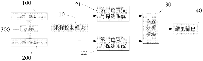
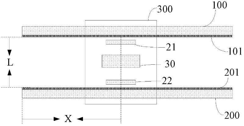
[0010] combine Figure 1 to Figure 3 Describe this embodiment, a displacement detection system with the function of correcting torsion errors, the system includes a first standard grating 101, a second standard grating 201, a sampling control module 10, a first position signal detection system 21, and a second position signal detection system 22 and a location analysis module 30;

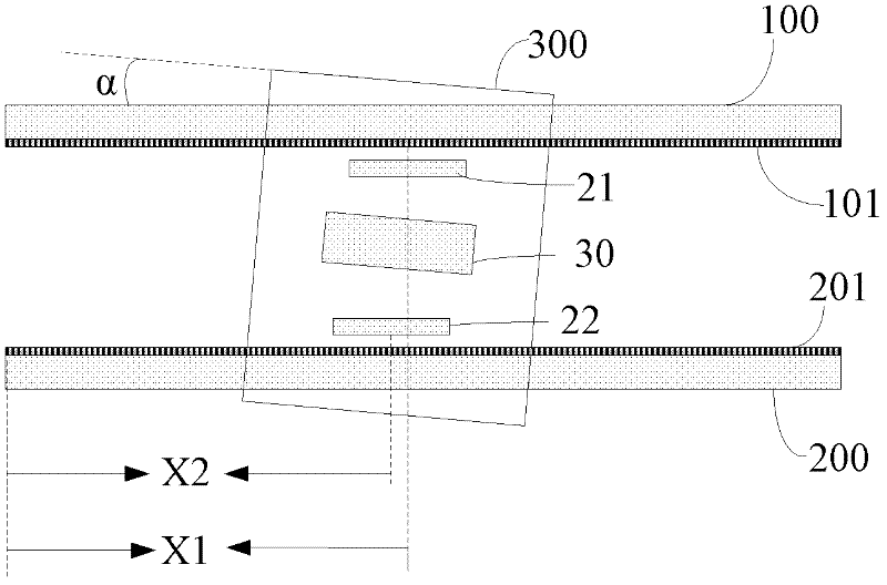
[0011] The position analysis module 30 receives position signals from the first position signal detection system 21 and the second position signal detection system 22, and the first position signal detection system 21 and the second position signal detection system 22 are unified by the sampling control module 10 The acquisition signal is sent out, and the position analysis module 30 analyzes and compares the displacement signals of the moving body 300 obtained from the first position signal detection system 21 and the second position signal detection system 22 relative to the first standard grating...


PUM


Abstract

The invention relates to a displacement detection system, in particular to a displacement detection system with a twist error correcting function. The problem that the measurement precision of a measuring instrument cannot be fully used because of the mechanical structure precision or the mounting precision of a machine tool while the traditional measurement technology is designed according to the measurement precision of the measuring instrument is solved. The system comprises a first standard raster, a second standard raster, a sampling control module, a first position signal probing system, a second position signal probing system and a position analyzing module, wherein the first position signal probing system and the second position signal probing system send sampling signals through the sampling control module together; and the position analyzing module weighs the two displacement signals and averagely calculates the displacement value of a moving body by analyzing and comparing the displacement signals from the first position signal probing system and the second position signal probing system. The displacement detection system is used for improving reading stability and self-detection ability of a measurement system, and eliminating or reducing a twist error to the greatest extent at the same time.

Description

technical field [0001] The invention relates to a displacement detection system, in particular to a displacement detection system with the function of correcting torsion errors. Measuring system for measuring lengths with high precision and stability. Background technique [0002] The grating line displacement measurement system is mainly used as the position feedback element in the closed-loop control in the numerical control. Its accuracy and reliability affect the machining accuracy. The advantage of the full-closed loop compared with the semi-closed loop is mainly that it can eliminate transmission errors. For machining tool position and workpiece Direct measurement of position. The accuracy of grating rulers at home and abroad has been able to meet higher measurement accuracy requirements, but the installation accuracy of domestic machine tools is not high enough, making it difficult for the high-precision advantages of high-precision measuring instruments to be fully ...

Claims


Application Information

Patent Timeline
IPC IPC(8): G01B11/04G01B21/22
Inventor 曾琪峰吴宏圣乔栋孙强卢振武
Owner CHANGCHUN INST OF OPTICS FINE MECHANICS & PHYSICS CHINESE ACAD OF SCI
Why Eureka
Try Eureka