Rail structure of precision numerical control machine tool

A precision CNC, machine tool technology, applied in metal processing machinery parts, large fixed members, measuring/indicating equipment, etc., can solve the quality problems of machined parts, track straightness errors, and inability

Pending Publication Date: 2020-07-10
HEFEI UNIV
View PDF0 Cites 0 Cited by
  • Summary
  • Abstract
  • Description
  • Claims
  • Application Information

AI Technical Summary

Problems solved by technology

[0003] Some CNC machine tools require that the spindle head can move to any position in the operation plane in the X and Y directions, that is, to drive the tool installed on the spindle head to move to any position on the operation plane to process the workpiece to be processed; in order to achieve the above purpose The most common design is to set the cross rail assembly on the bed. However, this track structure has poor bending resistance and rigidity, and cannot meet the requirements of modern precision CNC machine tools; There are two columns on the side, and the beam is set on the ...

Method used


Image

  • Rail structure of precision numerical control machine tool
  • Rail structure of precision numerical control machine tool
  • Rail structure of precision numerical control machine tool

Examples


Embodiment Construction

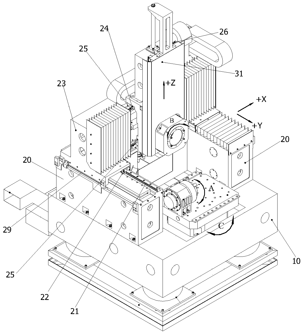
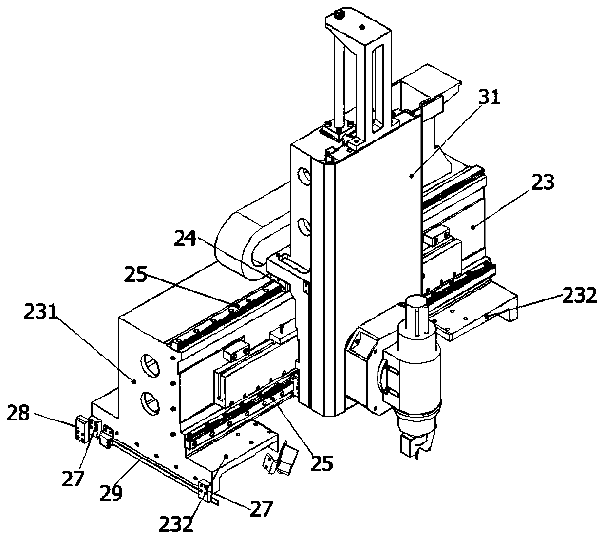
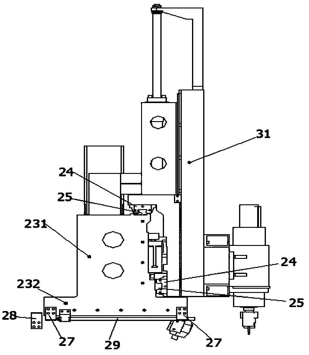
[0010] combine Figure 1-Figure 3 , a track structure of a precision numerical control machine tool, two side boxes 20 are symmetrically arranged on the upper end surface of the bed 10, a first linear guide rail 21 is fixed on the side box 20, and two first linear guide rails 21 on both sides Arranged in parallel and the length direction is parallel to the Y direction, the first slider 22 forms a sliding fit with the first linear guide rail 21, the two ends of the beam 23 are respectively fixedly connected with the first sliders 22 on both sides, and the beam 23 is provided with a second Two linear guide rails 25, the length direction of the second linear guide rail 25 is arranged parallel to the X direction, the second slider 22 forms a sliding fit with the second linear guide rail 25, and the second slider 22 is provided with a third straight line parallel to the Z direction The guide rail 26, the sliding seat 31 and the third linear guide rail 26 form a sliding fit. Compar...


PUM


Abstract

The invention aims to provide a high-bending-resistance high-rigidity rail structure of a precision numerical control machine tool. According to the rail structure, two side boxes are symmetrically arranged on the upper end face of a machine tool body, first linear guide rails are fixed to the side boxes correspondingly, the two first linear guide rails on each of the two sides are arranged in parallel, and length directions of the two first linear guide rails on each of the two sides are parallel to the Y direction, first sliding blocks are in sliding fit with the first linear guide rails, the two ends of a cross beam are fixedly connected with the first sliding blocks on the two sides correspondingly, second linear guide rails are arranged on the cross beam, length directions of the second linear guide rails are parallel to the X direction, a second sliding block is in sliding fit with the second linear guide rails, a third linear guide rail parallel to the Z direction is arranged onthe second sliding block, and a sliding seat is in sliding fit with the third linear guide rail. According to the scheme, the cross beam is arranged at the upper portion of the two side boxes and synchronously acts along with the first sliding blocks, so that the high bending resistance of external load heavy loads in the X, Y and Z directions can be borne, the torsion error between the X axis and the Y axis is reduced, and the rigidity and precision of the numerical control machine tool during cutting machining are guaranteed.

Description

technical field [0001] The invention relates to the technical field of numerical control machine tools, in particular to a track structure of a precision numerical control machine tool. Background technique [0002] With the development of mechanical cutting processing in the direction of integration, high speed, high rigidity and high precision, multi-axis CNC machining has become the mainstream of modern advanced manufacturing technology. As an important part of CNC machine tools, the track structure of machine tools has a significant impact on the The rigidity of the structure and its dynamic characteristics also directly affect the machining accuracy and product quality of the entire machine tool. [0003] Some CNC machine tools require that the spindle head can move to any position in the operation plane in the X and Y directions, that is, to drive the tool installed on the spindle head to move to any position on the operation plane to process the workpiece to be proces...

Claims


Application Information

Patent Timeline
IPC IPC(8): B23Q1/01B23Q17/24
CPCB23Q1/015B23Q1/017B23Q17/24
Inventor 赵茂俞罗熙淳秦强甄冒发蒋克荣蒙争争田一鸣戴淮初叶潮流
Owner HEFEI UNIV
Why Eureka
Try Eureka