Filter switching module for optical projection system

A switching module and optical projection technology, applied in optics, optical components, installation, etc., can solve problems such as inability to take into account brightness and color accuracy, and achieve the effect of automatically adjusting image output brightness and switching brightness quickly

Inactive Publication Date: 2013-12-11
ASIA OPTICAL CO INC
View PDF5 Cites 0 Cited by
  • Summary
  • Abstract
  • Description
  • Claims
  • Application Information

AI Technical Summary

Problems solved by technology

[0004] The technical problem to be solved by the present invention is to provide a light filter for an optical projection system that can automatically adjust the output brightness of an image in view of the defect that the liquid crystal projection system in the prior art cannot take into account the brightness and color accuracy in different image modes. switch module

Method used


Image

  • Filter switching module for optical projection system
  • Filter switching module for optical projection system
  • Filter switching module for optical projection system

Examples


Embodiment Construction

[0016] The foregoing and other technical contents, features and effects of the present invention will be clearly presented in the following detailed description of preferred embodiments with accompanying drawings.

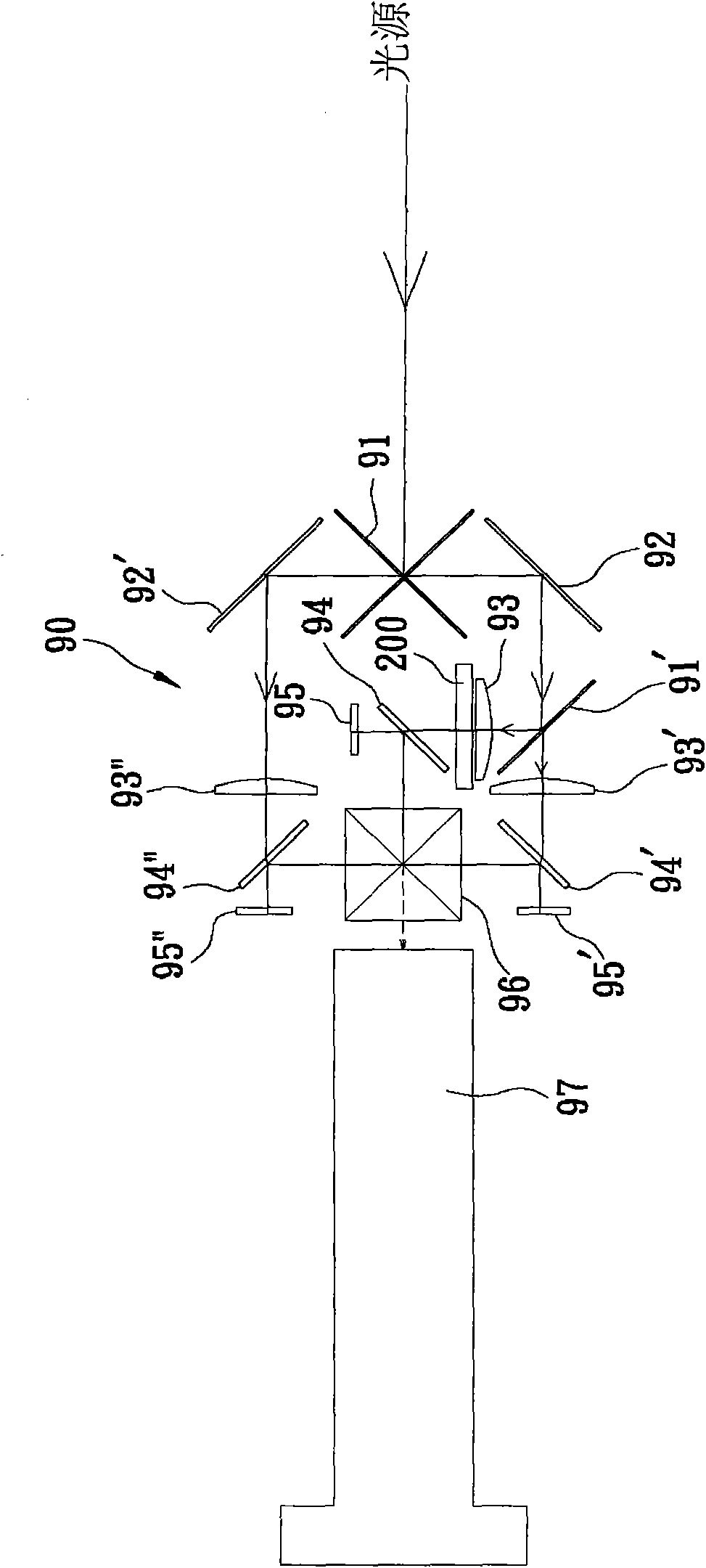
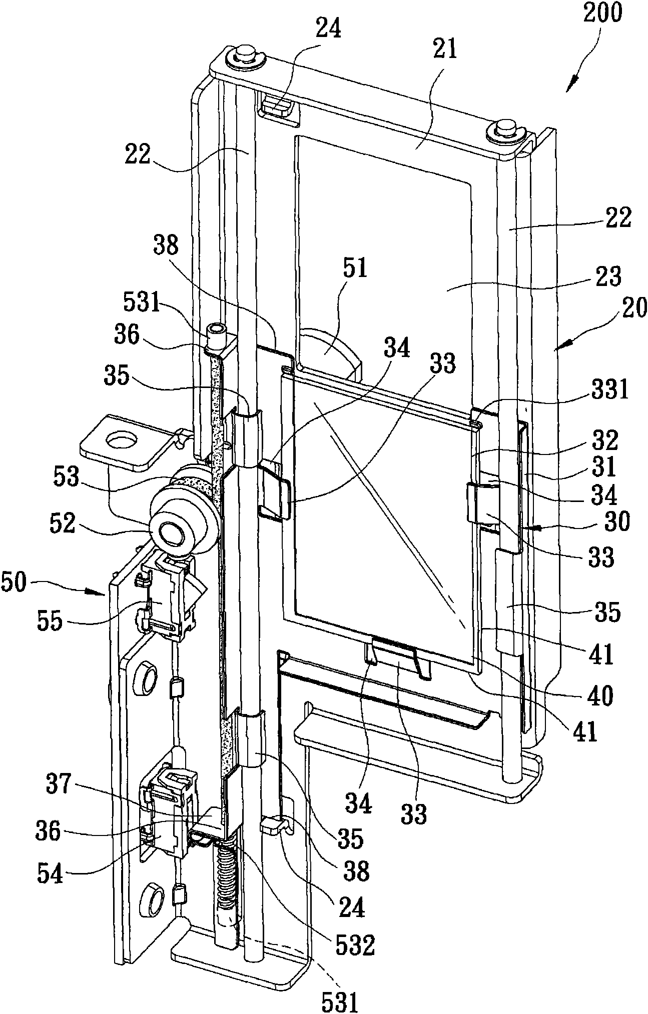
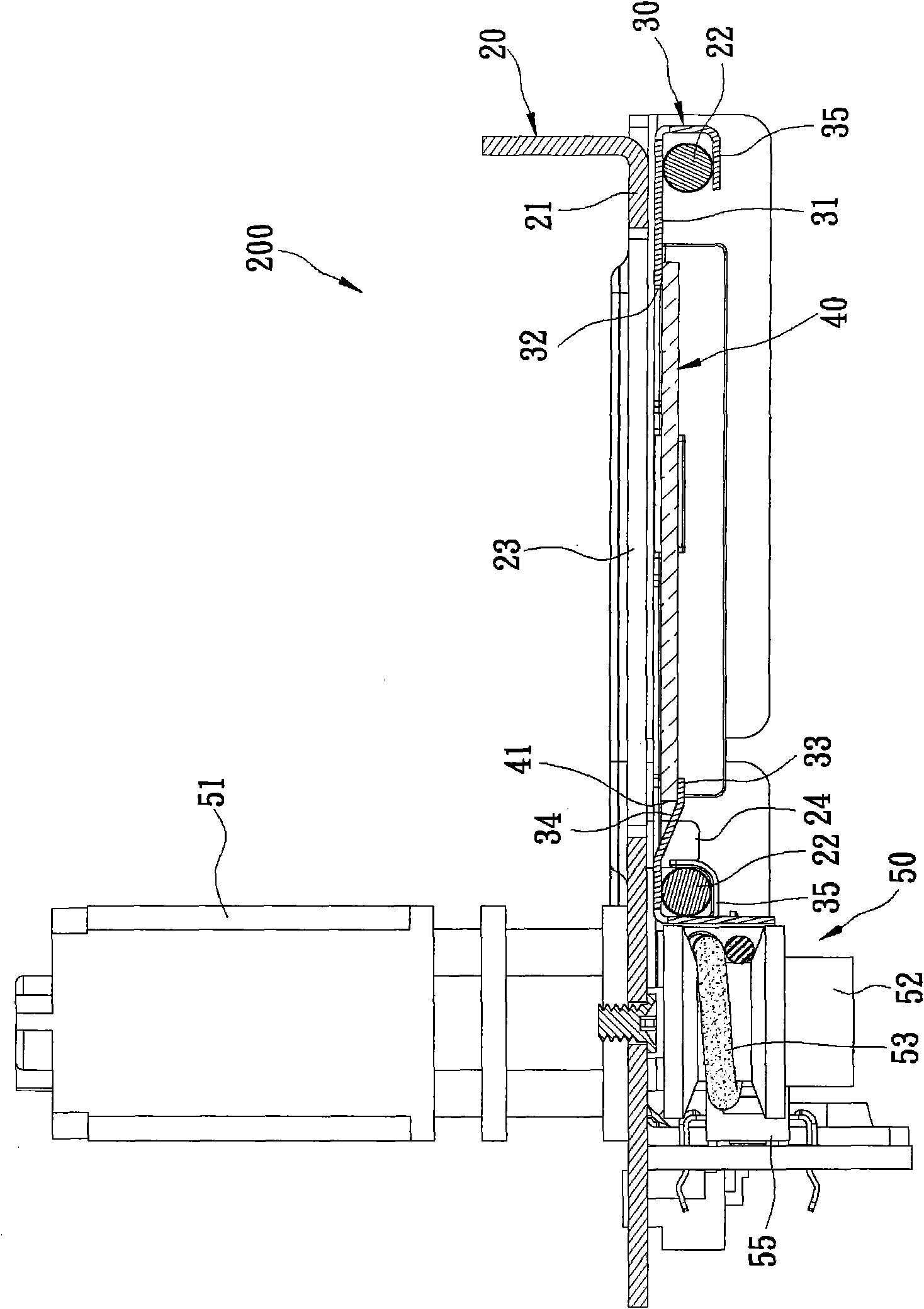
[0017] Such as figure 1 , 2 As shown in , 3, the preferred embodiment of the filter switching module 200 for the optical projection system of the present invention is applied in the optical projection system 90 used by the projector.

[0018] The optical projection system 90 includes two beam splitters 91, 91', two mirrors 92, 92', three collecting mirrors (Collimator Lens) 93, 93', 93", three polarizing beam splitters (Polarizing BeamSplitter, PBS) 94, 94', 94", three reflective liquid crystal panels (LCOS panel) 95, 95', 95", a prism 96 for combining light, and a projection lens 97.

[0019] In this embodiment, these beam splitters 91, 91' are designed to allow yellow-green light with a wavelength of 505-590 nm to pass through the collector mirror 93, the polar...


PUM


Abstract

The invention relates to a filter switching module for an optical projection system, which comprises a fixed base, a movable base, an optical filter and a driving unit. The fixed base comprises two guide rails and a light hole between the two guide rails. The movable base comprises a plurality of sliders, two stay rope fixing portions and an optical filter hole, wherein the sliders are respectively sleeved on the guide rails, the stay rope fixing portions are arranged at an interval along the guide rails, and the optical filter hole corresponds to the light hole. The optical filter is arranged on the movable base and covers the optical filter hole. The driving unit comprises a motor, a sheave and a stay rope, the sheave is arranged between the stay rope fixing portions, and two ends of the stay rope are respectively fixed onto the stay rope fixing portion and wound on the sheave. The stay rope is pulled by the movable base through the sheave so as to move relative to the light hole.

Description

technical field [0001] The invention relates to a filter module in an optical system, in particular to a filter switching module used in an optical projection system. Background technique [0002] Taiwan Patent Certificates No. I332588, No. I322323, No. I318074, and No. I306517 are all previous cases that have been approved by the applicant of this case and involve liquid crystal projection systems, and have disclosed Liquid Crystal On Silicon (LCOS for short) Technology, the main principle of these liquid crystal projection systems is to separate the beam emitted by the light source into three primary color beams of red, green and blue through a special dichroic mirror, and then let the beams of each color pass through a dedicated liquid crystal panel to form images of each color, and then synthesize images of each color to produce the final image output. [0003] The above system performs well in the output of two-dimensional (2D) images. However, in recent years, the ent...

Claims


Application Information

Patent Timeline
Patent Type & Authority Patents(China)
IPC IPC(8): G02B7/00G02B27/18
Inventor 蔡宗谋柯兆阳
Owner ASIA OPTICAL CO INC
Why Eureka
Try Eureka