Air cleaning device, air cleaning method using the air cleaning device, and air cleaning system

a technology of air cleaning and air cleaning method, which is applied in the direction of life-saving devices, fire rescue, and infections, can solve the problems that air cleaning means cannot operate efficiently within a limited space, and achieve the effect of efficiently discharged, efficient heat transfer, and efficient discharg

Active Publication Date: 2016-02-25
JAPAN
View PDF4 Cites 18 Cited by
  • Summary
  • Abstract
  • Description
  • Claims
  • Application Information

AI Technical Summary

Benefits of technology

[0019]In the thus configured air cleaning device according to the present invention, the air inlets / outlets are provided in the housing to which the illumination light source is attached, a fan is provided in the housing to generate a forced air flow inside and outside the housing through the air inlets / outlets and discharge heat from the illumination light source by the forced air flow to the outside of the housing, and the air cleaning means is provided in the middle of the flow path for the forced air flow in the housing. Accordingly, it is possible to discharge efficiently both the heat from the illumination light source and the heat from the air cleaning means by the forced air flow generated by the fan, and allow the illumination light source and the air cleaning means to be disposed in a compact and efficient manner. In addition, the air cleaning means cleans the air as the forced air flow taken by the fan from the air inlets / outlets into the housing and discharges forcibly the same to the outside from the air inlets / outlets. Accordingly, it is possible to allow the air cleaning means to operate and clean the air around the device in an efficient manner.
[0020]In addition, the air cleaning device has the light source support base made from a highly thermal-conductive member with the outer surface to which the illumination light source is fixed, and the inner surface of the light source support base opposite to the illumination light source constitutes the inner wall surface of the flow path. Accordingly, the heat generated by the illumination light source is transferred to the light source support base and is efficiently discharged by the forced air flow contacting the inner surface of the light source support base. As a result, it is possible to separately dispose the illumination light source and the air cleaning means with the light source support base therebetween, and efficiently transfer the heat from the illumination light source to the forced air flow passing through the air cleaning means through the light source support base.
[0021]The heat sink member made from a highly thermal-conductive member is protruded from the inner surface of the light source support base such that heat from the light source support base is discharged via the heat sink member to the forced air flow passing through the flow path. This allows the heat from the illumination light source to be discharged more efficiently to the forced air flow.
[0022]The illumination light source is made from an illumination LED, which allows power saving and increases power distribution to the air cleaning means to enhance the function of the air cleaning means. In addition, when the temperature of the LED rises to 90 degrees or more, the LED becomes reduced in light output and lifetime. However, the present invention allows efficient discharge of heat from the illumination LED by the forced air flow from the fan as described above, and thus prevents such a problem.
[0023]Provided as the air cleaning means are the photocatalyst facing the flow path and the UV light source irradiating the photocatalyst with light including ultraviolet rays. It is thus possible to clean by the action of the photocatalyst the air as the forced air flow taken into the housing, and then discharge the same to the outside, thereby realizing efficient cleaning of the air around the device. Although the UV light source is a light source prone to generate heat, the UV light source in the present invention is provided in the flow path for the forced air flow to allow the heat from the UV light source to be efficiently discharged in the same way as the heat from the illumination light source.
[0024]The UV light source is fixed to the inner surface of the light source support base or the heat sink member, and thus the heat generated by the UV light source can be efficiently discharged to the forced air flow through the light source support base and the heat sink member, in the same way as the heat generated by the illumination light source.

Problems solved by technology

However, the conventionally proposed illuminating device-cum-air cleaning device has a heat problem, that is, a problem that heat generated by both of the illumination light source and the air cleaning means persists within the casing, and a problem that the air cleaning means cannot operate efficiently within a limited space adjacent to the illumination light source.

Method used


Image

  • Air cleaning device, air cleaning method  using the air cleaning device, and air cleaning system
  • Air cleaning device, air cleaning method  using the air cleaning device, and air cleaning system
  • Air cleaning device, air cleaning method  using the air cleaning device, and air cleaning system

Examples


first embodiment

[0041]Embodiments of the present invention will be described below in detail with reference to the accompanying drawings. First, a first embodiment will be described with reference to FIGS. 1 and 2.

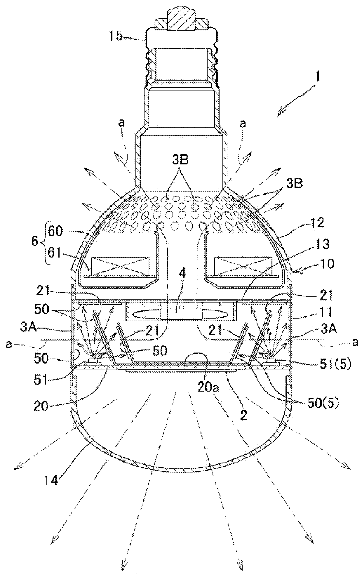
[0042]In an air cleaning device 1 of the first embodiment, as illustrated in FIG. 1, air inlets / outlets 3A and 3B are provided in a wall surface of a housing 10 to which an illumination light source 2 is to be attached, a fan 4 is provided in the housing 10 to generate forced air flows (shown by arrows a in FIG. 1) inside and outside the housing 10 through the air inlets / outlets 3A and 3B and discharge heat generated by the illumination light source 2 to the outside of the housing 10, and a photocatalyst 50 facing flow paths for the forced air flows a in the housing 10 and a UV light source 51 emitting light including ultraviolet rays to the photocatalyst 50 are provided as air cleaning means 5 in the middle of the flow paths.

[0043]The first embodiment is configured on the basis of the il...

second embodiment

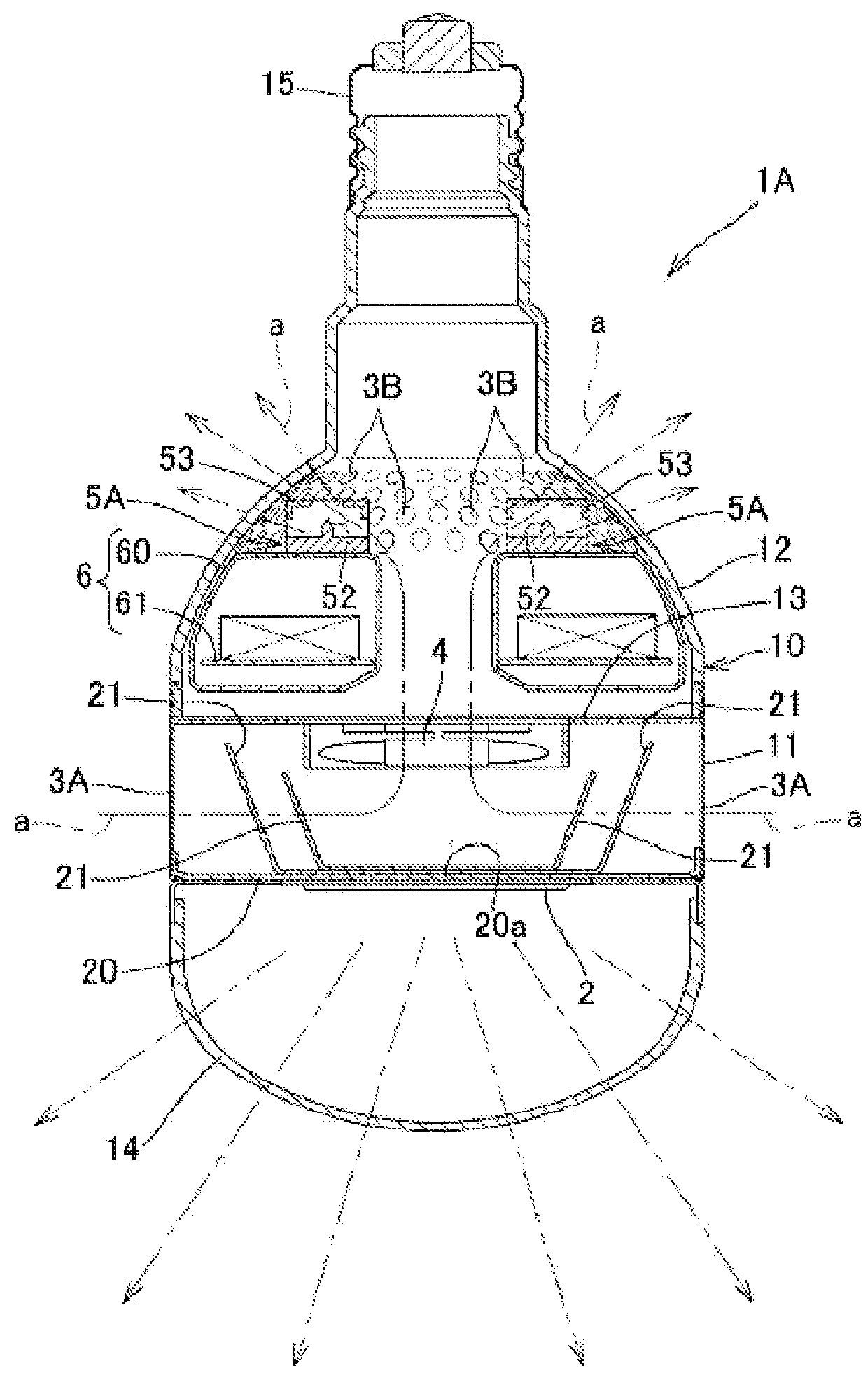
[0061]Next, a second embodiment will be described with reference to FIG. 3.

[0062]An air cleaning device 1A in this embodiment is provided with a means for generating ions or radical active species by discharge of a high voltage to be applied between electrodes 52 and 53 as air cleaning means 5A.

[0063]The air cleaning means 5A may be a means for applying a direct-current high voltage between the electrodes and generating negative ions by corona discharge as disclosed in JP-A No. 2006-034986 or JP-A No. 2007-305321, for example, or may be a means for applying an alternating-current voltage between electrodes opposed to each other with a dielectric body therebetween and generating positive and negative ions as described in JP-A No. 2002-095731, or may be a means for cooling electrodes by a Peltier cooler and applying a high voltage to condensed water to generate OH radicals covered by the water (for example, a “nanoe” device produced by Panasonic Corporation).

[0064]In particular, in th...

third embodiment

[0066]Next, a third embodiment will be described with reference to FIG. 4.

[0067]In an air cleaning device 1B of this embodiment, the light source support base 20 is composed of a centrally-bored plate-like base plate 22 and a support plate 23 overlapped and fixed to the base end-side surface of the base plate 22. The base plate 22 and the support plate 23 are both made from a highly thermal-conductive member of aluminum or the like. The illumination light source 2 is fixed to the leading end-side surface of the support plate 23 exposed to the opening 22a of the bored base plate 22.

[0068]The peripheral edge part of the support plate 23 is bent toward the base end side and is protruded in the flow paths for the forced air flows a in the same way as the heat sink member 21, so that heat from the illumination light source 2 can be efficiently released to the flow paths for the forced air flows a. The UV light source 51 as the air cleaning means 5 is also fixed to the base end-side surfa...


PUM

PropertyMeasurementUnit
wavelengthaaaaaaaaaa
temperatureaaaaaaaaaa

Abstract

To provide an illuminating device-cum-air cleaning device that solves a heat problem and allows efficient operation of an air cleaning means.
Air inlets/outlets 3A and 3B are provided in a wall surface of a housing 10 to which an illumination light source 2 is attached. A fan 4 is provided in the housing 10 to generate a forced air flow inside and outside the housing 10 through the air inlets/outlets 3A and 3B and discharge heat from the illumination light source 2 by the forced air flow to the outside of the housing 10. In the middle of a flow path for the forced air flow a within the housing 10, a photocatalyst 50 facing the flow path and a UV light source 51 irradiating the photocatalyst 50 with light including ultraviolet rays are provided as air cleaning means 5.

Description

TECHNICAL FIELD[0001]The present invention relates to an air cleaning device that includes an illumination light source and an air cleaning means and performs the function of an illuminating device.BACKGROUND ART[0002]There has been conventionally proposed an air cleaning device of this type composed of a light bulb-shaped casing that has at one end a base part attached to a power feeding part and connected to a commercial power source and has at the other end a blowing port and a light bulb; and an ozone generator that is housed in the casing such that the blowing port and a first electrode are opposed to each other to generate and release negative ions and ozone through the blowing port (refer to Patent Document 1).[0003]However, the conventionally proposed illuminating device-cum-air cleaning device has a heat problem, that is, a problem that heat generated by both of the illumination light source and the air cleaning means persists within the casing, and a problem that the air c...

Claims


Application Information

Patent Timeline
Patent Type & Authority Applications(United States)
IPC IPC(8): A61L9/20A61L9/22
CPCA61L9/22A61L9/205
Inventor WATANABE, TERUOWATANABE, HIDEMITSUWATANABE, HIROYUKIWATANABE, TAKAFUMI
Owner JAPAN
Why Eureka
Try Eureka