
Railway vehicle tractive transformer hanging beam

A technology for traction transformers and rail vehicles, which is applied in the directions of transformer/reactor installation/support/suspension, etc., which can solve problems such as complex dynamic stress and frequent acceleration loads of hanging beams, achieve high mechanical strength, improve welding automation level, and improve The effect of fatigue life

Inactive Publication Date: 2012-07-04
CRRC QINGDAO SIFANG CO LTD
View PDF1 Cites 6 Cited by
  • Summary
  • Abstract
  • Description
  • Claims
  • Application Information

AI Technical Summary

Problems solved by technology

[0005] During the high-speed running of the rail vehicle, because the change of the line requires different speed levels to pass, the vehicle needs to brake and accelerate frequently, resulting in frequent acceleration loads on the suspension beam, and its dynamic stress is also relatively complicated

Method used


Image

  • Railway vehicle tractive transformer hanging beam
  • Railway vehicle tractive transformer hanging beam
  • Railway vehicle tractive transformer hanging beam

Examples


Embodiment 1

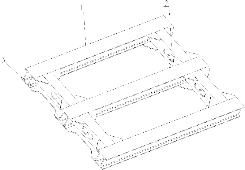
[0034] Example 1, such as Figure 1 to Figure 3 As shown, the rail vehicle traction transformer suspension beam mainly includes:

[0035] A frame structure composed of 3 beams 1 and 4 longitudinal beams 2 cross-connected,

[0036] The beams 1 are kept parallel to each other, and the longitudinal beams 2 are kept parallel to each other.

[0037] Welding is carried out at the connecting end between beam 1 and longitudinal beam 2,

[0038] The traction transformer of the rail vehicle is hoisted on the longitudinal beam 2 by bolts.

[0039] Among them, a reinforcing plate 3 is connected between two adjacent beams 1 , and a reinforcing plate 3 is connected between two adjacent beams 1 and longitudinal beams 2 .

[0040] The reinforcing plate 3 connected between two adjacent beams 1 is also connected to the adjacent longitudinal beams 2 at the same time.

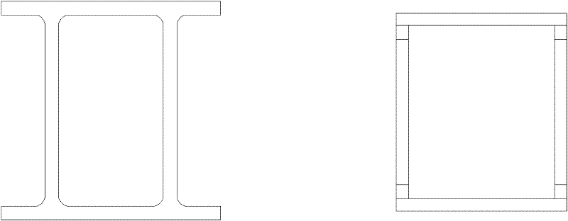
[0041] Both the beam 1 and the longitudinal beam 2 have aluminum alloy hollow profile structure, that is, the section of the...


PUM


Abstract

The invention relates to a railway vehicle tractive transformer hanging beam, which is of a frame type hanging structure. By means of welding connection between the structure of three transverse beams and the structure of four longitudinal beams, entire rigidity and mechanical strength of the hanging beam are improved, and using requirements of European standards for bearing load on abnormal working conditions are met. The hanging beam comprises a plurality of transverse beams and longitudinal beams in cross connection. The plurality of transverse beams keep parallel to each other, the plurality of longitudinal beams keep parallel to each other, and connection ends between the transverse beams and the longitudinal beams are welded. The transverse beams and the longitudinal beams are defined according to the directions in which the beams and a vehicle body form during installation, either transverse or longitudinal. A stiffening plate is connected between every two adjacent transverse beams. The transverse beams and the longitudinal beams adopt the welding connection mode, the stiffening plates are used for auxiliary reinforcement, and strength of the entire hanging beam is improved to bear acceleration load specified in EN12663 standards.

Description

technical field [0001] The invention is aimed at the improvement of the suspension beam structure of the traction transformer of the high-speed rail vehicle, and belongs to the field of machinery manufacturing. Background technique [0002] At present, the speed of rail vehicles put into use in China has reached more than 300 kilometers per hour. When the vehicle is running at a speed of more than 300 kilometers per hour, the force of the traction transformer suspension beam is more complicated. For performance indicators such as the structural strength of the traction transformer suspension beam The requirements are also getting higher and higher. [0003] The strength of the suspension beam of the current high-speed rail vehicle must meet the European standard-EN12663:2000, and there should be sufficient safety margin. As a main load-bearing part of the car body structure, the suspension beam of the traction transformer is particularly important in terms of strength, stif...

Claims


Application Information

Patent Timeline
Patent Type & Authority Applications(China)
IPC IPC(8): H01F27/06
Inventor 孙维光孙现亮田爱琴陈文宾丁叁叁周建乐马云双龚明
Owner CRRC QINGDAO SIFANG CO LTD
Learn More