Suspension end insulation structure with transformer coil inserted with shielding wire

A technology of transformer coils and shielded wires, which is applied in the direction of transformer/inductor coil/winding/connection, preventing/reducing unnecessary electric/magnetic influence, etc., and can solve the problems of difficult guarantee of reliability, waste of raw materials, increase in transformer volume, etc. problems, to achieve the effect of increasing the partial discharge inception voltage, reducing manufacturing costs, and reducing the size of the transverse oil passage

Inactive Publication Date: 2012-07-04
SHANDONG DACHI ELECTRIC
View PDF4 Cites 6 Cited by
  • Summary
  • Abstract
  • Description
  • Claims
  • Application Information

AI Technical Summary

Problems solved by technology

As a result, the volume of the transformer increases, raw ma

Method used


Image

  • Suspension end insulation structure with transformer coil inserted with shielding wire
  • Suspension end insulation structure with transformer coil inserted with shielding wire
  • Suspension end insulation structure with transformer coil inserted with shielding wire

Examples


Embodiment Construction

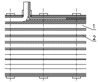
[0009] Accompanying drawing is a kind of specific embodiment of the present invention.

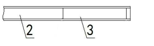
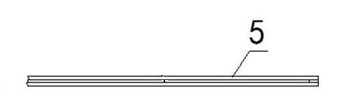
[0010] The insulating structure of the suspension end of the transformer coil inserted into the shielding wire of the present invention includes coil current-carrying wires 1 and coil shielding wires 2 distributed at intervals, the end of the coil shielding wire is connected to the cardboard strip 3, the suspension end of the coil shielding wire 2, the coil shielding wire The outer side of the contact between the wire 2 and the cardboard strip is covered with aluminum metallized crepe paper 5, the outer side of the cardboard strip is wrapped with Denison paper 4, and the floating end of the coil shielding wire 2 is rounded.

[0011] The insulation structure of the suspended end of the transformer coil inserted into the shielding wire includes coil current-carrying wire 1 , coil shielding wire 2 , cardboard strip 3 , Denison paper 4 and crepe paper 5 . The insulating structure of the floati...


PUM


Abstract

The invention discloses a suspension end insulation structure with a transformer coil inserted with a shielding wire. The suspension end insulation structure comprises a coil current carrying wire and a coil shielding wire distributed at an interval. An end part of the coil shielding wire is connected to a paperboard strip; aluminum metallization crepe papers are covered at outer sides of a suspension end of the coil shielding wire and the contact part of the coil shielding wire and the paperboard strip; a Denison paper is covered at the outer side of the paperboard strip; and the suspension end of the coil shielding wire is in a round corner structure. The invention has the advantages that an existing shielding suspension end which is not treated or is subjected to simple wrapping is changed into a standard insulation structure, so that a local discharge initial voltage at the suspension end is effectively increased, simultaneously the electric field intensity of two adjacent oil conduits at the shielding suspension end and a horizontal oil conduit size between two adjacent shielding suspension ends are reduced; the service life of the transformer is prolonged; and the production cost is lowered.

Description

technical field [0001] The invention relates to a floating end insulation structure in which a transformer coil is inserted into a shielding wire, which belongs to the transformer inner shielding-continuous coil shielding wire suspension end insulation structure, and belongs to an insulation wrapping structure. Background technique [0002] At this stage, due to the more stringent requirements of users on the partial discharge, service life and reliability of transformers, and the overhang of shielded wires is one of the reasons for the increase in partial discharge and the increase in the size of the adjacent two-wire cake oil passage, in order to control the local To ensure that the electric field strength of the adjacent wire cake shielding suspension end is within the allowable field strength range, it is necessary to thicken the turn insulation thickness of the current-carrying wire and shielding wire and the size of the adjacent shielding suspension end oil pass...

Claims


Application Information

Patent Timeline
IPC IPC(8): H01F27/32H01F27/36
Inventor 董景义李杰黄启锋
Owner SHANDONG DACHI ELECTRIC
Why Eureka
Try Eureka