Sealed structure of mini-type electronic dehumidifying and cooling machine

A technology of electronic dehumidifier and cooler, applied in the direction of cooling/ventilation of substation/switchgear, etc., can solve the problems of hidden danger of electrical safety, rising power consumption of dehumidification equipment, difficult exchange of cold and heat with large temperature difference, etc., to achieve reliability The effect of protection and power consumption reduction

Inactive Publication Date: 2012-07-04
叶秋诗 +2
View PDF5 Cites 37 Cited by
  • Summary
  • Abstract
  • Description
  • Claims
  • Application Information

AI Technical Summary

Problems solved by technology

The current situation of the power system is that the dehumidification effect of the indoor armored switchgear with a voltage level of 6kV and above is not good. Often the relative humidity in the switchgear room has reached 50% RH or even lower. After opening the armored switchgear, it is found that the electrical appliances in the cabinet There is condensation water on the equipment, indicating that this dehumidification method has electrical safety hazards, and due to the ventilation of the indoor and outdoor air of the switch, the power consumption of the dehumidification equipment has increased significantly
The dehumidification equipment of various indoor and outdoor terminal cabinets adopts the method of installing electric heating in the cabinet with natural ventilation or forced ventilation, and sometimes the second, third and fourth lead wires around the electric heater are prematurely aged or burned. and because the air inside and outside the cabinet communicates, frequent heating and dehumidification not only has poor dehumidification effect, but also keeps high power consumption
The electronic dehumidifiers installed in various indoor and outdoor terminal cabinets that are being promoted and tested by the power system, there is no installation position for the electronic dehumidifier due to the compact des

Method used


Image

  • Sealed structure of mini-type electronic dehumidifying and cooling machine
  • Sealed structure of mini-type electronic dehumidifying and cooling machine
  • Sealed structure of mini-type electronic dehumidifying and cooling machine

Examples


Embodiment Construction

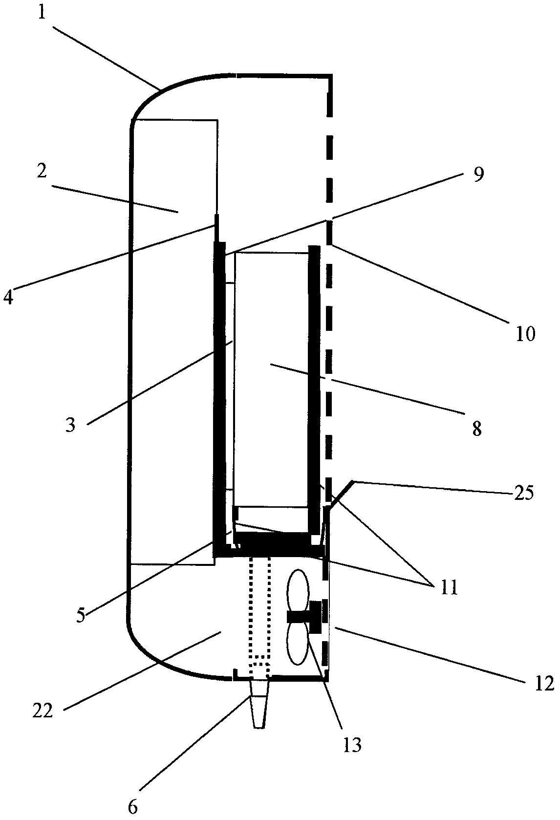
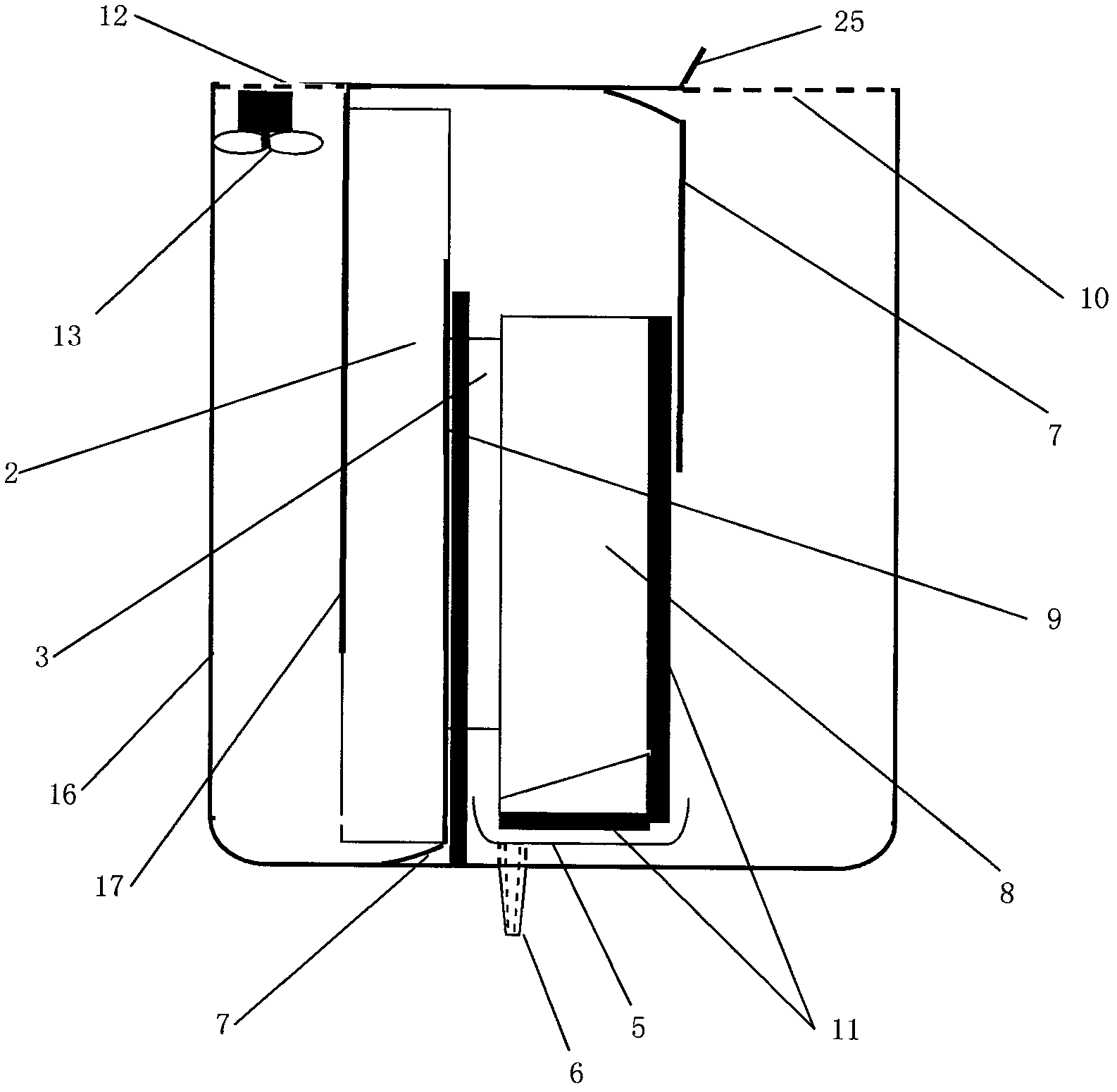
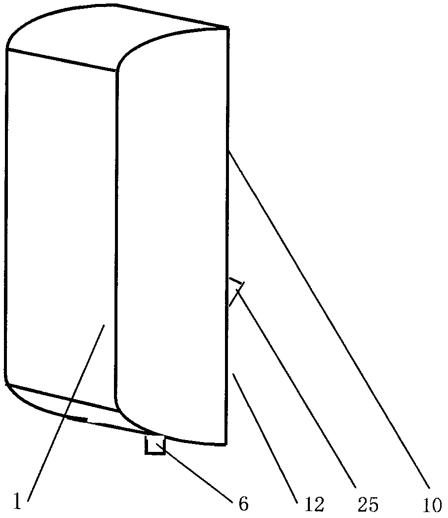
[0021] According to the installation position on the dehumidification and cooling equipment, the side of the equipment is divided into a miniature electronic dehumidification and cooling device and a miniature electronic dehumidification and cooling device is installed on the bottom panel of the equipment. Air inlet (12), 1 dry cold air outlet (10) and 1 dry cold air outlet deflector baffle (25), and a detachable box outer cover (1) is installed on the side, and there is a condensed water discharge pipe ( 6), the other parts of the miniature electronic dehumidification and cooling device (Figure 3) are completely closed, and the heat conduction paste is evenly coated on both sides of the upright electronic cooling plate (3), and the heat sink is square on the heating surface side of the electronic cooling plate Smooth backplane plane (14), the heating surface of the electronic cooling fin (3) is attached to the square smooth backplane plane (14) of the heat sink, and the other ...


PUM


Abstract

The invention provides a sealed structure of a mini-type electronic dehumidifying and cooling machine. A heat radiation face and a refrigerating face of a vertical electronic refrigerating sheet are sealed to be a wet air heating channel and a wet air condensing channel, which are mutually independent and are provided with vertical communicated upper parts. One end of a wet air leading channel is communicated with the lower part of the wet air heating channel, and the other end of the wet air leading channel is provided with a mini-type blower. The lower end opening of the wet air condensing channel is sealed, and a refrigerating face of the wet air condensing channel aligns to a dried cool air discharge hole which is arranged at a vertical position. A water collection hopper is arranged below a condensing sheet of the refrigerating face. A drain pipe of the water collection hopper is communicated to the outside of a shell box of the sealed structure of the mini-type electronic dehumidifying and cooling machine through leading of the water collection hopper. The installation on the lateral face or the bottom face outside an indoor armor switch cabinet or various terminal bins of an electric system with a 6-kV or above voltage class is met. The inside spaces of the armor switch cabinet and the terminal bins are not occupied. No interferences of a high voltage and a strong magnetic field exist. The equipment operation inside the armor switch cabinet and the terminal bins is not influenced by the maintenance and repair of the mini-type electronic dehumidifying and cooling machine.

Description

Technical field [0001] The invention relates to a closed structure of a miniature electronic dehumidification and cooling device installed on the outside of an indoor armored switch cabinet with a voltage level of 6kV and above in a power system and various indoor and outdoor terminal cabinets. In particular, the miniature electronic dehumidification and cooling device is installed in a closed structure outside the dehumidification and cooling equipment, which can meet the requirements of the dehumidification and cooling equipment without being forced to cooperate with power failure during the maintenance of the miniature electronic dehumidification and cooling device. The ambient temperature in the cabinet, the power consumption of the miniature electronic dehumidifier with closed structure is lower than that of the electronic dehumidifier installed in the same power terminal box cabinet that is currently popularized and tried in the power system, and the closed structure of t...

Claims


Application Information

Patent Timeline
IPC IPC(8): H02B1/56
Inventor 叶秋诗叶宏田军
Owner 叶秋诗
Why Eureka
Try Eureka