Laser scanning device

A laser scanning device, laser technology, applied in the direction of image communication, electrical components, etc., can solve the problems that affect the detection accuracy, cannot detect synchronously, and image scanning processing positions are different

Active Publication Date: 2015-03-25
IND TECH RES INST
View PDF3 Cites 0 Cited by
  • Summary
  • Abstract
  • Description
  • Claims
  • Application Information

AI Technical Summary

Problems solved by technology

[0005] In view of this, the present invention provides a laser scanning device to solve the problems in the prior art that there are too many components, occupying space, unable to detect synchronously, only the image in the central area is a clear image, and the position scanned by the actual laser beam and the charge-coupled device The problem that the scanning processing position of the image obtained by receiving the visible light beam is different and affects the detection accuracy

Method used


Image

  • Laser scanning device
  • Laser scanning device
  • Laser scanning device

Examples


Embodiment Construction

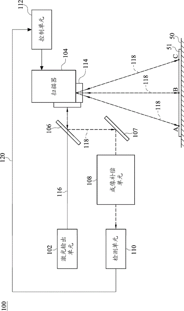
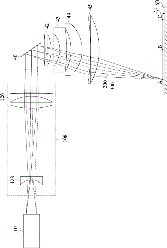
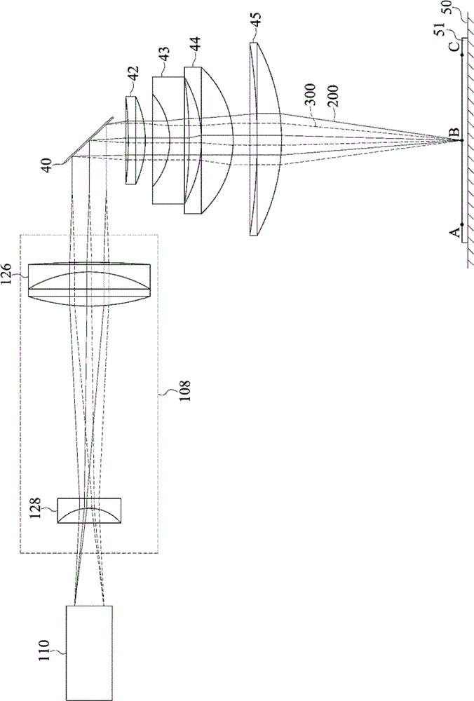
[0049] Please refer to figure 1 , which is a structural diagram of an embodiment of the laser scanning device disclosed in the present invention. The laser scanning device 100 is suitable for scanning the object 51 placed on the working platform 50. The object 51 includes a positioning point A, a positioning point B and a positioning point C, wherein the positioning point B is arranged between the positioning point A and the positioning point C and positioned Point B is the center point of the object 51 . In this embodiment, the laser scanning device 100 focuses on the positioning point B. As shown in FIG. The laser scanning device 100 is not focused on the positioning point A and the positioning point C. The imaging gap between the focal point of the laser scanning device 100 and the positioning point A can be, but not limited to, 300 micrometers (micrometer, μm) to 2000 microns, and the imaging gap between the focal point of the laser scanning device 100 and the positionin...


PUM


Abstract

A laser scanning device includes a laser output unit, a scanner, a light splitting unit, an imaging compensation unit, a detection unit, and a control unit. A scanning focusing unit included in the scanner focuses a laser beam emitted by the laser output unit to scan an object. A visible light beam received by the canning focusing unit is reflected by the light splitting unit and is incident into the imaging compensation unit. Next, the detection unit receives the visible light beam passing through the imaging compensation unit, and outputs a detection signal. The control unit adjusts the detection signal according to the wavelength of the visible light beam, the wavelength of the laser beam, the scanning focusing unit, and the imaging compensation unit. Therefore, the laser scanning device may compensate the aberration and the dispersion caused when the visible light beam passes through the scanning focusing unit.

Description

technical field [0001] The invention relates to a laser scanning device, in particular to a laser scanning device capable of compensating the aberration and dispersion caused by a visible light beam passing through a scanning focusing unit. Background technique [0002] Laser processing technology is a method of using laser beams to scan and produce marks on objects. There are many types of lasers available in the industry for processing, such as carbon dioxide lasers, semiconductor lasers, and diode lasers. [0003] The production line of the traditional laser processing process is mainly divided into three blocks, the first block is the positioning area, the second block is the processing area, and the third block is the inspection area. However, before laser processing, the production line will first use a Charge Coupled Device (CCD) in the positioning area for positioning, then perform laser processing in the processing area, and finally use a charge coupled device for ...

Claims


Application Information

Patent Timeline
Patent Type & Authority Patents(China)
IPC IPC(8): H04N1/04H04N1/00
Inventor 林于中李闵凯刘松河
Owner IND TECH RES INST
Why Eureka
Try Eureka