Device for centring and guiding the rotation of a turbomachine shaft

An engine and turbine technology, applied in the field of rotating devices, can solve the problems of large volume of centering and guiding devices

Active Publication Date: 2012-07-04
SN DETUDE & DE CONSTR DE MOTEURS DAVIATION S N E C M A
View PDF7 Cites 2 Cited by
  • Summary
  • Abstract
  • Description
  • Claims
  • Application Information

AI Technical Summary

Problems solved by technology

[0011] A specific object of the present invention is to provide a simple, effective and economical solution to the problem of too large a volume of centering and guiding devices of the prior art

Method used


Image

  • Device for centring and guiding the rotation of a turbomachine shaft
  • Device for centring and guiding the rotation of a turbomachine shaft
  • Device for centring and guiding the rotation of a turbomachine shaft

Examples


Embodiment Construction

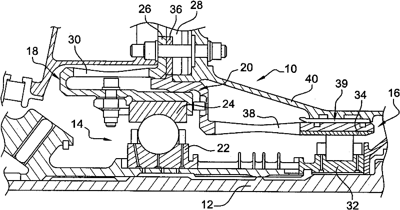
[0037] see figure 1 , figure 1 A prior art device 10 is shown for centering and guiding the rotation of a shaft 12 of a high pressure compressor of a turbine engine, comprising two relatively flexible annular supports mounted around this shaft 12 18 and 20 carry ball bearing 14 and roller bearing 16 . In the art, this device 10 is known as a flex-flex "dual" bearing.

[0038]The ball bearing 14 has a series of balls guided in a race defined by an inner ring 22 fastened to the shaft 12 and an outer ring 24 fastened to the shaft 12 . One end of said annular support 18, said annular support 18 has an annular flange 26 at its other end for fastening to an annular flange 28 of the intermediate housing of the turbine engine. The support 18 has a generally C-shaped cross-section and includes an elastically deformable annular portion 30 which imparts a certain amount of flexibility to the support.

[0039] The roller bearing 16 is mounted downstream of the ball bearing 14 and comp...


PUM


Abstract

Device (110) for centring and guiding the rotation of a turbomachine shaft (112), comprising a roller bearing (116) and a ball bearing (114) which are mounted around the shaft and carried respectively by first and second flexible annular supports (120, 118), and an oil film compression damper (139) comprising a rigid annular support (140) arranged around the roller bearing, the supports for the ball bearing and for the damper and the roller bearing being stacked transversely and extending around one another

Description

technical field [0001] The invention relates to a device for centering and guiding the rotation of a shaft, in particular in a turbine engine. Background technique [0002] Typically, the turbine engine shaft is centered and guided in rotation by two upstream and downstream support devices, one of which may comprise two rolling bearings mounted side by side. [0003] In the art, the guide bearing is usually referred to as a "single" bearing when the bearing which guides the shaft has only one rolling bearing, such as a roller bearing or a ball bearing, which is supported by a rigid ring extending around the shaft. carried by. [0004] When a pilot bearing has two rolling bearings, the pilot bearing is often referred to as a "double" bearing, which usually includes a roller bearing and a ball bearing. [0005] The ball bearing of the double bearing is carried by an annular support with an amount of flexibility so that it deforms in operation and allows the ball bearing to m...

Claims


Application Information

Patent Timeline
Patent Type & Authority Applications(China)
IPC IPC(8): F01D25/16F16C27/04
CPCF05B2230/604F01D25/164F16C27/04F05D2230/64F16C19/545F16C2360/23F16C19/54F16C27/045F16C19/49F16C27/00
Inventor 伊万·盖·罗思恩
Owner SN DETUDE & DE CONSTR DE MOTEURS DAVIATION S N E C M A
Why Eureka
Try Eureka