Connection assembly for a sensor assembly and sensor assembly

A sensor device and connection device technology, applied in the direction of measuring devices, instruments, measuring instrument components, etc., can solve the problems of excessive injection molding, difficult positioning, increased mold wear, etc., and achieve the effect of rapid positioning

Active Publication Date: 2012-07-04
ROBERT BOSCH GMBH
View PDF6 Cites 6 Cited by
  • Summary
  • Abstract
  • Description
  • Claims
  • Application Information

AI Technical Summary

Problems solved by technology

The edges of the bent webs between the two crimped connections must be sealed in the injection mold by unfavorable stepped seals, but positioning is thus difficult, which leads to increased wear of the mold or overmolding
This overmolding in turn has a negative effect on subsequent processes, such as the resistance welding process for contacting the sensor element

Method used


Image

  • Connection assembly for a sensor assembly and sensor assembly
  • Connection assembly for a sensor assembly and sensor assembly
  • Connection assembly for a sensor assembly and sensor assembly

Examples


Embodiment Construction

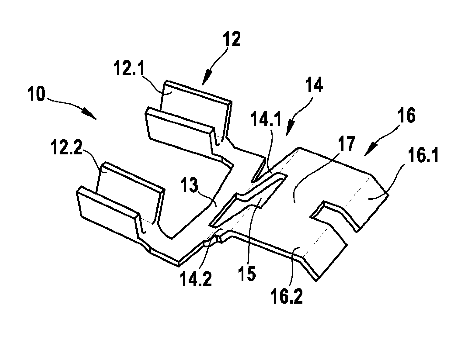
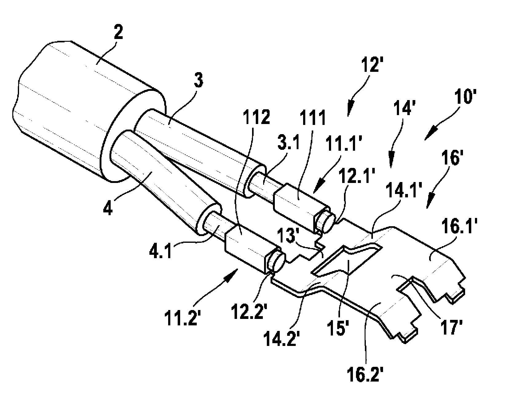
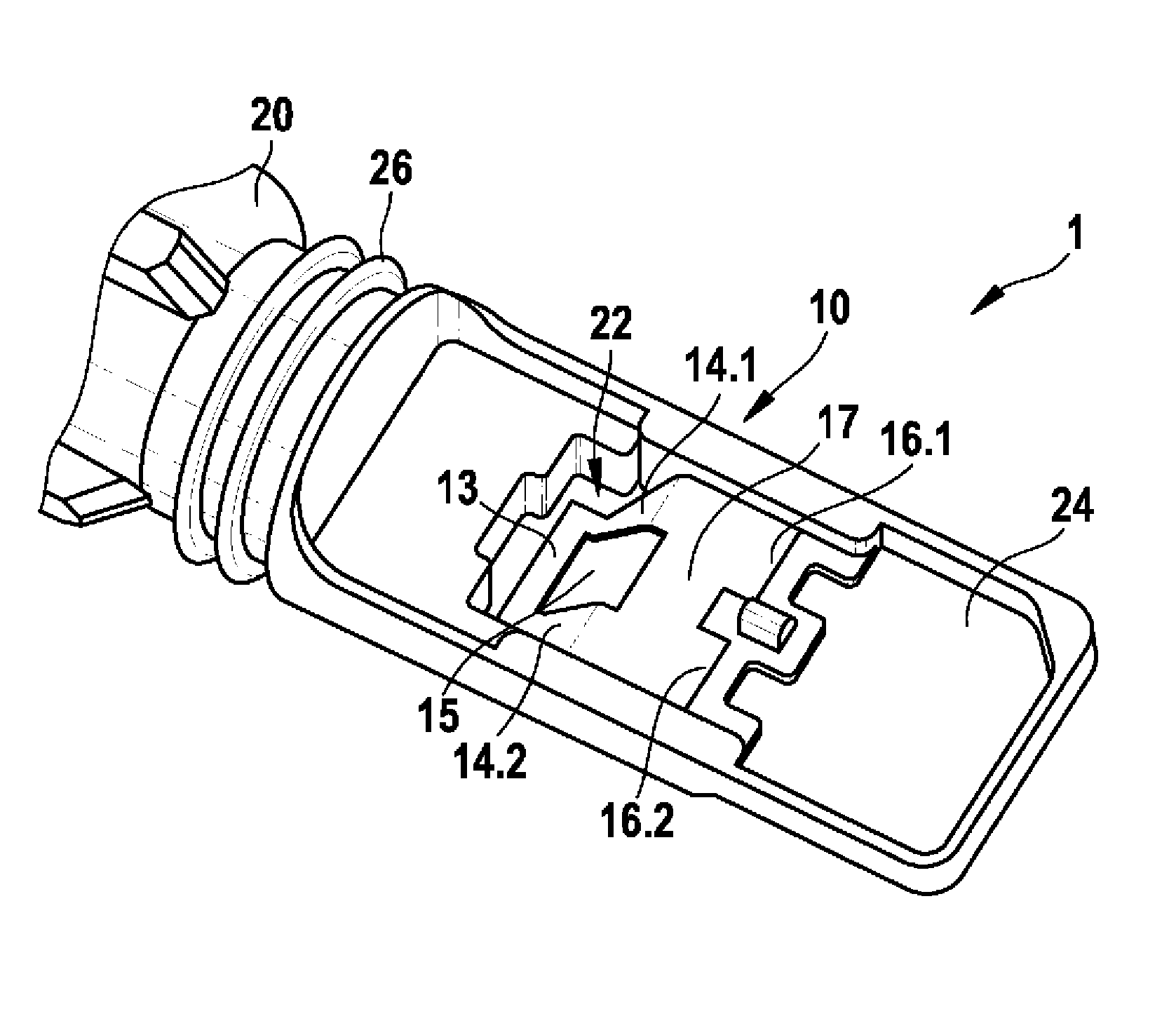
[0022] figure 1 and 2 A schematic perspective view of a first exemplary embodiment of a connecting element 10 is shown in each case for use in image 3 and 4 A connection device 1 for a sensor device according to the invention is shown in FIG. here, figure 1 The connection element 10 is shown before it is connected with a two-wire connection cable 2, and figure 2 The connection element 10 is shown after the double crimped connection structure 11.1, 11.2 has been created with the two-wire connection cable 2.

[0023] as available from figure 1 As seen in or 2, the first embodiment of the connecting element 10 comprises in the first contact region 12 two first connecting parts 12.1, 12.2 embodied as curled shoulders, the first connecting part 12.1 , 12.2 are connected to each other through the first connecting piece 13 . as especially available from figure 2As seen in , the two first connectors 12.1, 12.2 are electrically and mechanically connected to the core wires 3,...


PUM


Abstract

The invention relates to a connection assembly (1) for a sensor assembly having a connection element (10) which is electrically and mechanically connected to one end (3.1, 4.1) of at least one wire (3, 4) of a connection cable (2) in a first contacting region (12) and can be electrically and mechanically connected to a sensor element in a second contacting region (16), wherein the connection element (10) is at least partially enclosed by a plastic overmold (20) which has a window-shaped recess (22) in a transition region (14) between the first contacting region (12) and the second contacting region (16) which is sealed in the injection moulding die during the injection process of the plastic overmold (20) and a corresponding sensor assembly.; According to the invention, a positioning opening (15) is arranged in the transition region (14) such that the connection element (10) can be positioned in the injection moulding die and the transition region (14) surrounding the positioning opening (15) is sealed flat in the injection moulding die to create the window-shaped recess (22).

Description

technical field [0001] The invention relates to a connection device for a sensor device of the type according to independent claim 1 and to a corresponding sensor device. Background technique [0002] For example, laid-open document DE 10 2005 012 709 A1 discloses a magnetic field sensor, in particular a rotational speed sensor and / or a steering sensor for a vehicle wheel or for a drive train of a vehicle. The described magnetic field sensor has a carrier for the sensor element and optionally further sensor components. The carrier is designed as a plastic injection-molded part and has, in the region of its read-side end face, a pocket-like recess in which the sensor element is supported at least in the direction of the injection molding during the final extrusion-molding of plastic And thus prevent mechanical damage. The connecting device for the described magnetic field sensor has a connecting element which has two connecting pieces in the first contact area, which are ea...

Claims


Application Information

Patent Timeline
Patent Type & Authority Applications(China)
IPC IPC(8): G01D11/30
CPCG01D11/245G01D11/30G01P1/026
Inventor R.施泰因布林克S.克卢格S.奥尔特曼S.舒尔策D.马蒂J.利贝特劳F.韦舍伊特尔J.贝耶斯多费尔
Owner ROBERT BOSCH GMBH
Why Eureka
Try Eureka