Method of manufacturing molded stator of dynamo electric machine

A technology for molding stators and rotating electrical machines. It is applied in the manufacture of stator/rotor bodies, motor generators, and electromechanical devices. It can solve problems such as chip stress and achieve the effect of reducing stress.

Inactive Publication Date: 2012-07-04
MITSUBISHI ELECTRIC CORP
View PDF5 Cites 8 Cited by
  • Summary
  • Abstract
  • Description
  • Claims
  • Application Information

AI Technical Summary

Problems solved by technology

[0009] However, stress is generated on the chip due to the caulking process of the concavo-convex part.

Method used


Image

  • Method of manufacturing molded stator of dynamo electric machine
  • Method of manufacturing molded stator of dynamo electric machine
  • Method of manufacturing molded stator of dynamo electric machine

Examples


Embodiment approach 1

[0037] Embodiment 1 of the manufacturing method of the mold stator of the electric rotating machine of this invention is demonstrated using drawing.

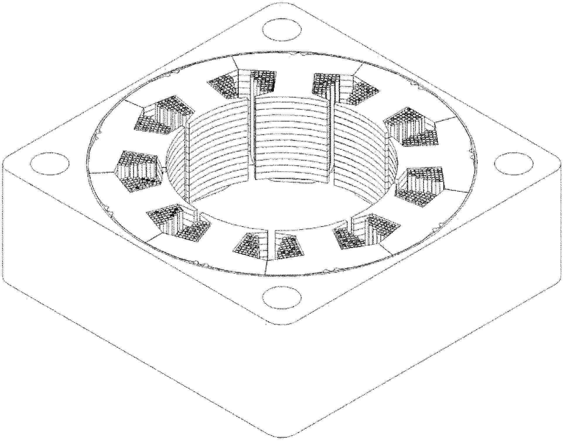
[0038] figure 1 It is a sectional view of the molded stator 1 of the rotating electrical machine of the present invention. Should figure 1 shows a cross section of a molded stator 1 manufactured by combining a plurality of divided laminated cores 71 around which coils 3 are wound in an annular shape and fixing them with film tape 4, and then putting them in Mold and use resin 5 to fix around.

[0039] Hereinafter, the manufacturing method of the molded stator 1 will be described in order.

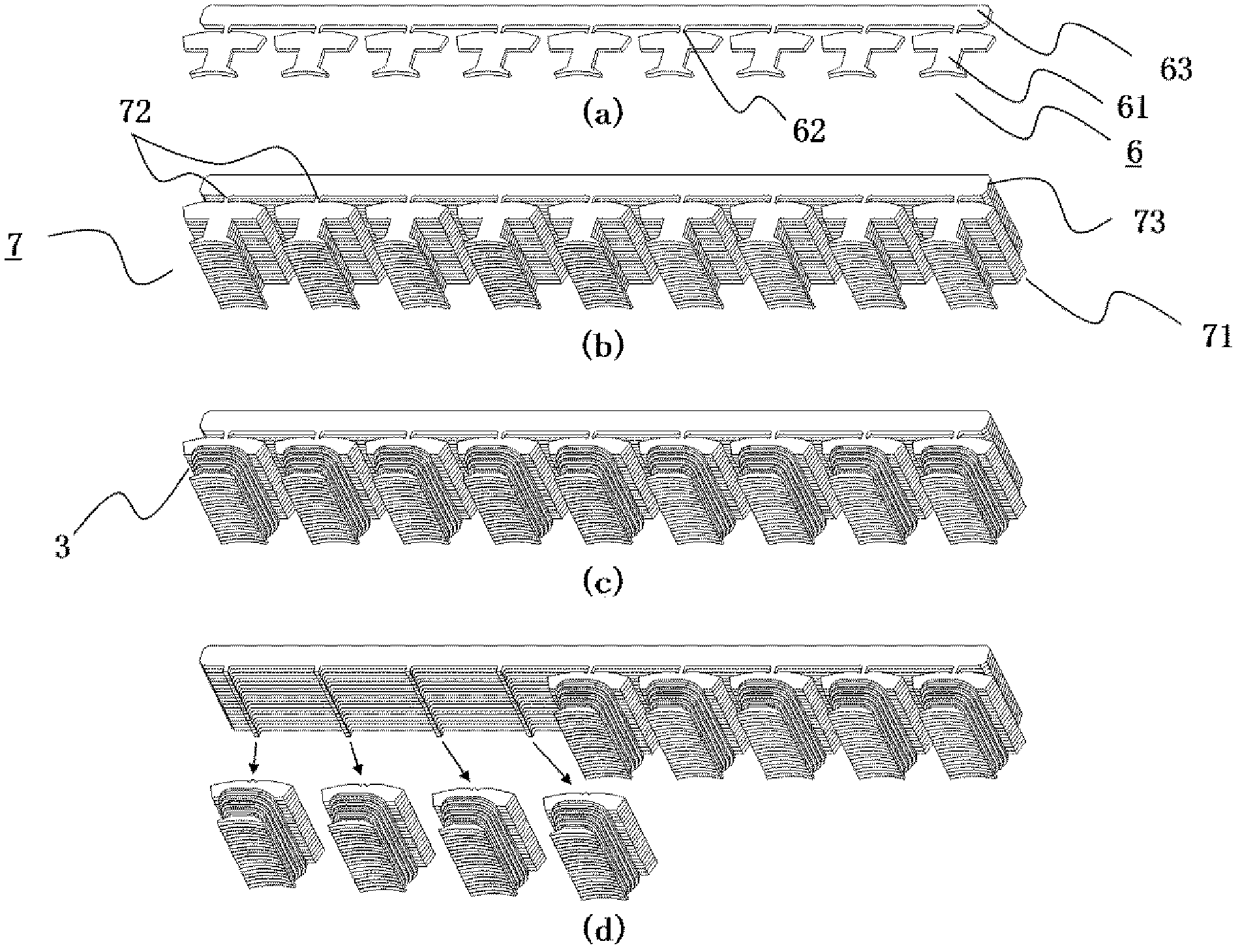
[0040] figure 2 It is a figure showing a lamination process, a winding process, and a cutting process.

[0041] figure 2 (a) is a diagram showing the shape of one core sheet 6 .

[0042] figure 2 (b) is a diagram showing a divided laminated core group structure 7 in which a plurality of core sheets 6 are laminated.

[0043] figu...

Embodiment approach 2

[0072] Embodiment 2 of the manufacturing method of the molded stator of the electric rotating machine of this invention is demonstrated using drawing.

[0073] In addition, only the parts different from Embodiment 1 will be described, and the common parts will be omitted.

[0074] Figure 7 It is a cross-sectional view of the divided laminated core group structure 107 according to the second embodiment cut along a direction perpendicular to the longitudinal direction and along the lamination direction at a position including the bridge portion 62 .

[0075] In Embodiment 1, a fixing method is employed in which core sheets 6 are directly stacked without providing a member for fitting vertically adjacent core sheets 6 , and coil 3 is wound around the teeth.

[0076] In the present embodiment, recesses 65 are provided on the upper surface of connecting portions 163 of each core sheet, and protrusions 64 are provided on the lower surface.

[0077] exist Figure 7 In the present...

Embodiment approach 3

[0083] Embodiment 3 of the manufacturing method of the mold stator of the electric rotating machine of this invention is demonstrated using drawing. In addition, only the parts different from Embodiment 1 and Embodiment 2 are described, and the common parts are omitted.

[0084] Figure 8 (a) and (b) are figures which show the modification of the concave part and convex part provided in the upper and lower surfaces of the connection part of a core material.

[0085] Figure 9 It is a cross-sectional view in which the lamination connection portion 273 of the divided laminated core assembly structure formed by alternately laminating the core sheets 206 and 2061 along the longitudinal direction and along the lamination direction is divided into two.

[0086] exist Figure 8 On the connecting portion 263 of the core sheet 206 shown on the lower side of (a), convex portions 264 and openings 265 are alternately provided from the right side as shown in the figure.

[0087] In add...


PUM


Abstract

A method of manufacturing the molded stator of a dynamo electric machine comprises a lamination step for constituting a split lamination core group structure (7) by laminating a plurality of core sheets (6) in each of which a plurality of core pieces (61) are bonded to one coupling part through a bridge (62), a winding step for winding a coil around the tooth of each split lamination core (71) of the split lamination core group structure (7), a cutting step for cutting the split lamination core (71), around which a coil is wound, at the bridge and separating the split lamination core, a temporary fixing step for shaping a plurality of split lamination cores (71) into an annular stator (2) and fixing the stator temporarily, and a molding step for setting the stator (2) in a die by inserting a mold mandrel (10) to the inner circumferential side of the stator, and fixing the outer circumferential surface of the stator (2) with resin.

Description

technical field [0001] The present invention relates to a method of manufacturing a molded frame type stator of a rotating electric machine composed of divided laminated cores. Background technique [0002] Conventionally, as a stator of a rotating electric machine, there is a laminated fixed core composed of a plurality of divided laminated cores divided in units of magnetic pole teeth, and two or more core pieces are laminated and fixed. [0003] The teeth of the divided laminated cores are provided with winding portions perpendicular to the radial direction of the laminated fixed core, and a plurality of divided laminated cores are arranged in an annular combination with the winding portions facing the center direction. In addition, a stator is formed as an integral structure by covering the ring-shaped structure so as to surround them and pressing in the inner diameter direction, and a rotary electric machine using this stator has been disclosed. [0004] In addition, a...

Claims


Application Information

Patent Timeline
Patent Type & Authority Applications(China)
IPC IPC(8): H02K1/12H02K3/44H02K15/02H02K15/12
CPCH02K2201/09H02K15/12H02K1/148H02K15/022Y10T29/49009Y10T29/49012Y10T29/49071Y10T29/49073Y10T29/49078
Inventor 汤谷政洋三宅展明中原裕治长谷川治之青海豪则土屋文昭小牧亮子
Owner MITSUBISHI ELECTRIC CORP
Why Eureka
Try Eureka