Sorting screen of combine harvester

A combine harvester and cleaning sieve technology, which is applied to agricultural machinery and implements, threshing equipment, applications, etc., can solve the problem that the difference in the working load of the cleaning sieve aggravates the damage of the cleaning sieve, the cleaning surface is not fully utilized, and the cleaning Unbalanced force on the left and right sides of the sieve, etc., to achieve good cleaning effect, uniform force, and small size

Inactive Publication Date: 2012-07-11
JIANGSU WORLD AGRI MACHINERY
View PDF6 Cites 12 Cited by
  • Summary
  • Abstract
  • Description
  • Claims
  • Application Information

AI Technical Summary

Problems solved by technology

The cleaning sieve on the existing combine harvester is a front and rear vibration type. During the grain cleaning process, the grain on the sieve surface flows from front to back, and there are many cleaning sieves at the material inlet, resulting in unbalanced forces on the left and right sides of the cleaning sieve. , the cleaning sieve is easily damaged, and the great difference in the workload between the left and the right of the cleaning sieve also aggravates the damage of the cleaning sieve
In addition, the material on the sieve surface is uneven, and when the harvester turns, the grain on the sieve surface is prone to blockage, and the cleaning surface of the cleaning sieve is not fully utilized, which greatly reduces the grain cleaning effect
In order to achieve a better cleaning effect, the method of lengthening the cleaning sieve is usually adopted to increase the cleaning surface, but such a structure leads to an increase in the length and size of the harvester, an increase in the volume and weight of the whole machine, and a decrease in reliability. Increased costs

Method used


Image

  • Sorting screen of combine harvester
  • Sorting screen of combine harvester
  • Sorting screen of combine harvester

Examples


Embodiment Construction

[0014] The present invention will be further described below in conjunction with drawings and embodiments.

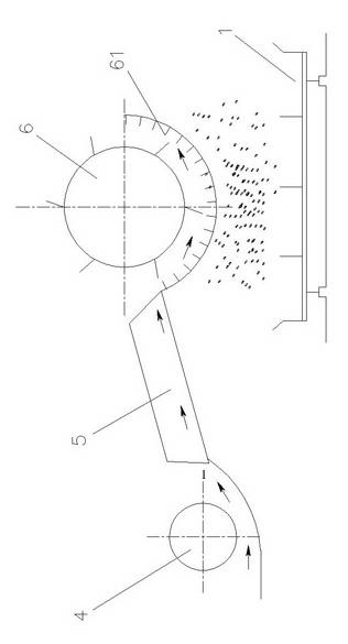
[0015] Such as figure 1 As shown, it is the direction of crop flow. After the crops are harvested by the harvesting device 4, the crops are transported to the threshing device 6 through the conveying device 5 as indicated by the single arrow, and the separation of grains and stems is completed, and the preliminary cleaning through the concave plate 61 is completed. Impurities such as grains and some small stalks fall into the sieve body 1 of the present invention for further screening. During the falling process of impurities such as grains and some small stalks, the fan located outside one end of the sieve body 1 (not shown in the figure) out) to winnow the falling grains and some small stalks, the double arrows indicate the left and right vibration direction of the sieve body 1.

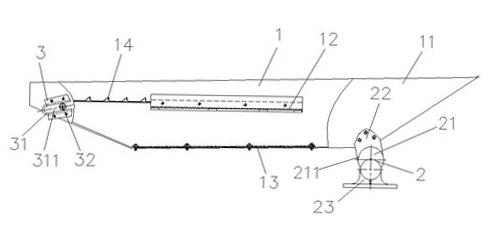
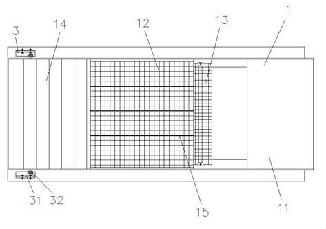
[0016] Such as figure 2 , image 3 As shown, the present invention includes a sieve ...


PUM


Abstract

The invention discloses a sorting screen of a combine harvester, which comprises a screen body, an eccentric drive mechanism and sliding mechanisms, wherein the eccentric drive mechanism is disposed below one end of a screen body, and the sliding mechanisms are symmetrically disposed on two sides of the other end of the screen body. The screen body comprises a screen frame, an upper mesh screen, a lower mesh screen, a corrugated plate and a plurality of sorting baffles. The eccentric drive mechanism comprises a crankshaft, a pair of connecting plates and a pair bearing blocks, wherein two ends of the crankshaft are supported inside the bearing blocks through bearings respectively, a crankshaft journal is fixedly respectively connected with the lower end of every one of the connecting plates in one pair, and the upper ends of the connecting plates in one pair are fixedly connected with the front bottom and the rear bottom of the screen frame respectively. The sliding mechanisms comprise sliding seats and rollers, wherein the rollers supported at the front and the rear of the screen frame are inlaid inside the sliding seats. The sorting screen is simple and compact in structure, threshed grains fall onto the whole screen surface and flow from the left to the right, and the left and the right of the screen are evenly stressed so that the screen is less prone to damage. The screen is small in size and large in sorting area, so that the overall weight of the harvester is lowered greatly, the overall reliability of the harvester is improved, and the grains are sorted effectively and efficiently.

Description

technical field [0001] The invention relates to a screening device for grains harvested by a combine harvester, in particular to a left and right vibrating cleaning screen, which belongs to the technical field of agricultural machinery. Background technique [0002] The cleaning screen is an important part of the combine harvester. It plays the role of screening and cleaning grains in the harvester. Its working principle is: through the vibration of the screen body, the threshed grains and straw are layered, and then filtered through the screen. At the same time, the dust, small straw and other debris are blown away under the action of the fan, so as to realize the grain cleaning. In order to fully filter the grain in layers and achieve the best cleaning effect, it is required that the cleaning sieve has a large cleaning area and a high vibration frequency. The cleaning sieve on the existing combine harvester is a front and rear vibration type. During the grain cleaning pr...

Claims


Application Information

Patent Timeline
Patent Type & Authority Applications(China)
IPC IPC(8): A01F12/44
Inventor 张铁立刘景张艺辉史文娟
Owner JIANGSU WORLD AGRI MACHINERY
Why Eureka
Try Eureka