Denitration method in SNCR (selective non catalytic reduction) furnace for exactly realizing temperature window tracking

An accurate and denitrification technology, applied in the field of denitration, can solve the problems of high cost, large emission, and variable injection volume.

Active Publication Date: 2012-07-11
SHANGHAI TECHSPRAY ENG
View PDF2 Cites 14 Cited by
  • Summary
  • Abstract
  • Description
  • Claims
  • Application Information

AI Technical Summary

Problems solved by technology

However, the effect on the toxic and harmful gases emitted is very limited.
In the past, there are two denitrification methods, one is the CNR method, which has a complex structure and is suitable for large boilers, and its cost is expensive; the other is the SNCR method, which is suitable for small boilers and its cost i

Method used


Image

  • Denitration method in SNCR (selective non catalytic reduction) furnace for exactly realizing temperature window tracking
  • Denitration method in SNCR (selective non catalytic reduction) furnace for exactly realizing temperature window tracking
  • Denitration method in SNCR (selective non catalytic reduction) furnace for exactly realizing temperature window tracking

Examples


Embodiment Construction

[0023] In order to further understand the characteristics of the present invention, the present invention will be further described below in conjunction with accompanying drawing:

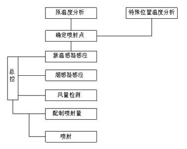
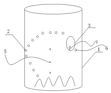
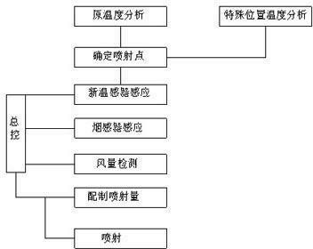
[0024]An SNCR furnace denitrification method that accurately realizes temperature window tracking. First, the position of the injection point 2 must be determined according to the temperature curve obtained by the original temperature sensing device 5 in the furnace hall 1. Of course, for a special furnace hall 1, there will be For some special corners, set the temperature sensor separately, monitor it separately, and get the temperature change curve after long-term induction, so as to determine whether to install the injection point, and install a temperature sensing detector around the injection point in the furnace. For the design of the injection point, we put aside the previous design ideas, and used to design it at the tuyere 7, or try to make the sprayed liquid parallel to the wind, but for t...


PUM


Abstract

The invention relates to a denitration method in an SNCR (selective non catalytic reduction) furnace for exactly realizing temperature tracking, aiming at exactly realizing jetting by correspondingly adjusting the jetting quantity of reducing agent in the furnace according to furnace temperature change, furnace fire burning state and burning stage timely. In order to achieve the aim, the denitration method in the SNCR furnace for exactly realizing temperature tracking is adopted so that jetting points are determined according to a temperature curve obtained by temperature induction equipment which is originally in the furnace, and temperature inductive probes are arranged around the jetting points required in the furnace. The method comprises the following steps of: (1) during jetting, firstly judging the work states of the furnace by the temperature inductive equipment which is originally in the furnace, wherein the work states comprise a blow-in state, a normal work state and a blow-out state; (2) after the state is confirmed, extracting the temperatures around the corresponding jetting points; computing the temperatures, and according to the change curve of the different work states, obtaining the temperatures of the corresponding points in the furnace during the next jetting; and (3) computing jetting quantity according to the temperatures, sending out a command by means of master control, and jetting according to quantity.

Description

technical field [0001] The invention relates to a denitrification method, in particular to an SNCR furnace denitrification method for accurately realizing temperature tracking. Background technique [0002] Air pollution mainly comes from flue gas emissions from industrial boilers, such as iron and steel metallurgy, chemical production, and thermal power generation, all of which are heavy polluting units. In traditional or existing technologies, the prevention and control of flue gas emissions mainly include gravity dust removal, centrifugal dust removal, bag dust removal, electrostatic dust removal, wet dust removal, etc., all of which have played a certain role in reducing dust pollution in flue gas emissions. However, the effect on the toxic and harmful gases emitted is very limited. In the past, there are two denitrification methods, one is the CNR method, which has a complex structure and is suitable for large boilers, and its cost is expensive; the other is the SNCR m...

Claims


Application Information

Patent Timeline
IPC IPC(8): B01D53/79B01D53/56
Inventor 徐文辉邹贞秦昂
Owner SHANGHAI TECHSPRAY ENG
Why Eureka
Try Eureka