High performance agitation tank bottom paddle

A stirring tank and high-performance technology, applied in the field of bottom paddles, can solve the problems of uneconomical, increased energy consumption, large bottom paddle diameter, etc., and achieve the effects of good stirring effect, increased scouring force, and significant energy saving and consumption reduction.

Inactive Publication Date: 2012-07-11
SHENYANG ALUMINIUM MAGNESIUM INSTITUTE
View PDF1 Cites 1 Cited by
  • Summary
  • Abstract
  • Description
  • Claims
  • Application Information

AI Technical Summary

Problems solved by technology

Although the problem of sediment accumulation can be improved, the diameter of the bottom paddle is too large, and the energy consumption increases too much, which is very uneconomical

Method used


Image

  • High performance agitation tank bottom paddle
  • High performance agitation tank bottom paddle
  • High performance agitation tank bottom paddle

Examples


Embodiment 1

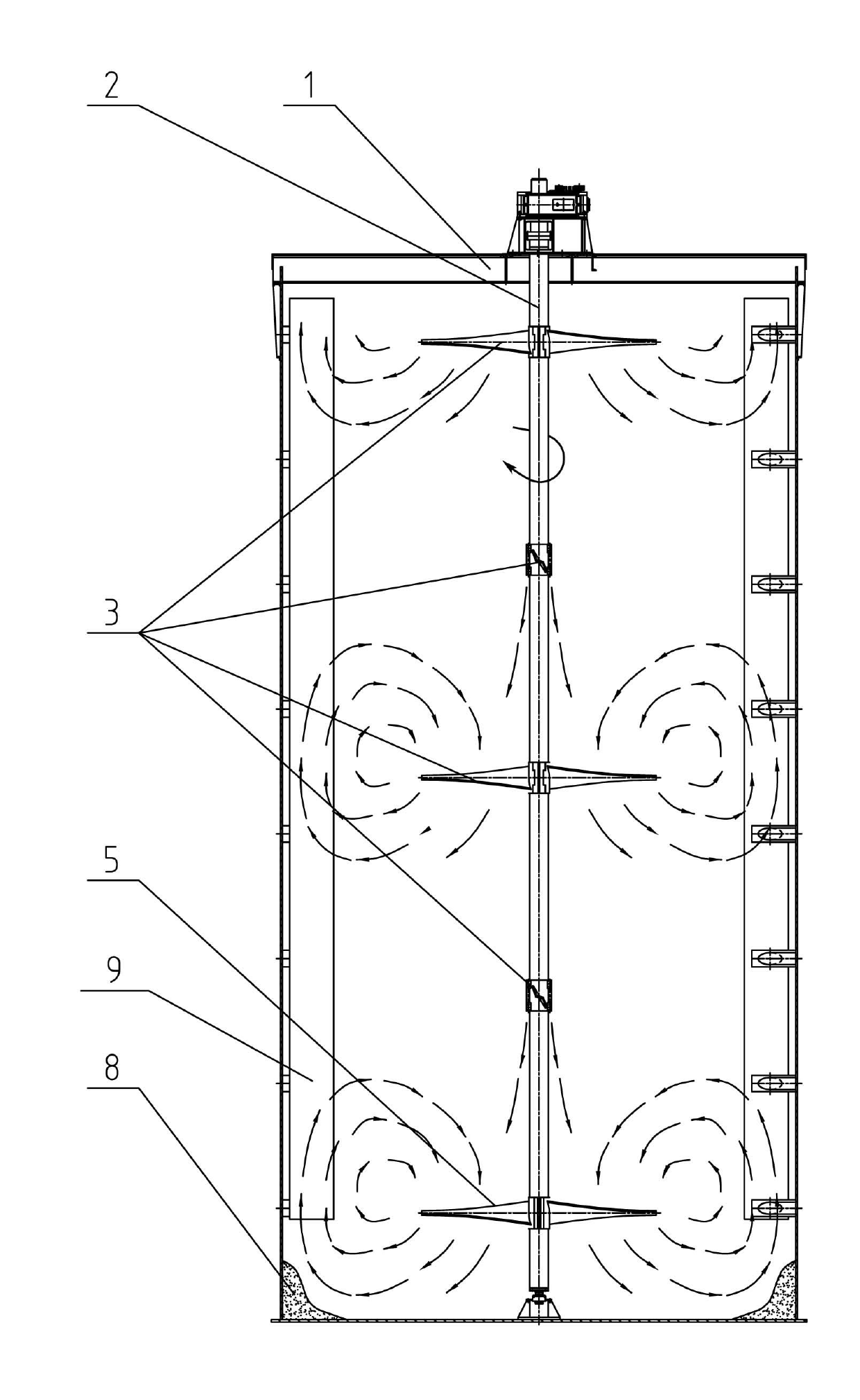
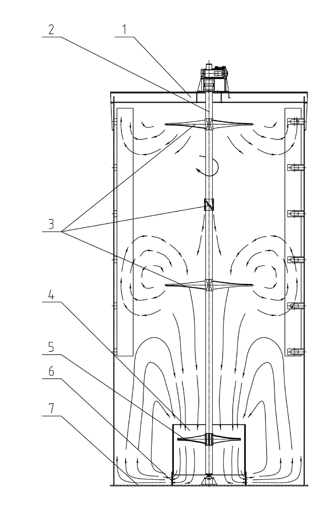
[0018] Such as figure 2 The shown bottom paddle of the high-performance stirring tank of the present invention includes a paddle 5, and the outer circle of the paddle 5 is provided with a lower steel plate cylinder 4, and the lower steel plate cylinder 4 is fixed on the bottom plate 7 of the tank through the support plate 6, and the lower steel plate circle The barrel 5 is cylindrical, the diameter of the lower steel plate cylinder 4 is 1.02-1.1 times the diameter of the paddle 5, the height of the lower steel plate cylinder 4 is equal to the diameter of the paddle 5, and the paddle 5 is located on the upper part of the lower steel plate cylinder 4 2 / 5 to 1 / 4 of the position, the distance between the lower steel plate cylinder 4 and the tank bottom plate 7 is 1 / 40 to 1 / 15 of the diameter of the paddle 5, and the diameter of the paddle 5 is 0.4 to 0.6 times the diameter of the stirring tank 1. There are 2 to 6 leaves 5, and the paddle 5 is a folding paddle.

[0019] The uppe...

Embodiment 2

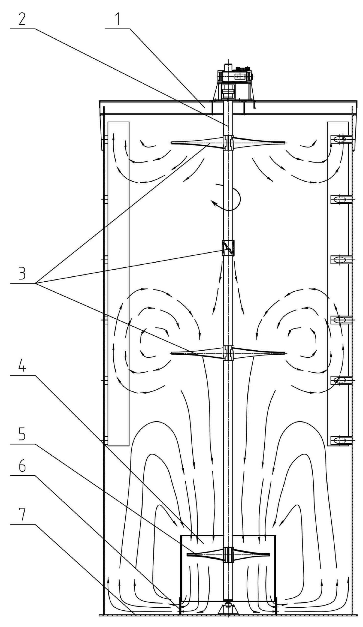
[0021] The lower steel plate cylinder in Example 1 is in the shape of a conical tube, in the shape of a bell mouth, with an opening that is small at the top and large at the bottom, and the extension line of the opening at the lower end points to the bottom corner of the groove. Others are with embodiment 1.


PUM


Abstract

The invention relates to a bottom paddle and especially to a high performance agitation tank bottom paddle. The agitation tank bottom paddle comprises a blade; a cycle of lower steel plate cylinder is arranged at the periphery of the blade and fixed on a tank bottom plate through a facing plate. The advantages of the invention are as follows: a good stirring effect is obtained, the lower steel plate cylinder forms a collector which centralizes liquid flows generated by a stirring paddle to a same direction, thereby enabling flow velocity to become faster and more intensive, a scouring force to be substantially increased and stirring strength to be strengthened; the diameter of the blade is 0.4 to 0.6 time of the diameter of a tank body, energy consumption of the blade is far less than that of a 0.7 time prolonged paddle, so the paddle provided in the invention has remarkable effects in energy saving and consumption reduction; an obvious effect on eliminating deposition and scab is achieved, the gap between the lower steel plate cylinder and the tank bottom plate is maintained at an appropriate small distance, and when liquid flows pass through the gap, flow velocity becomes faster but resistance loss is small, thereby exerting intensive scouring on tank bottom and corners and eliminating deposited materials.

Description

technical field [0001] The invention relates to a bottom paddle, in particular to a high-performance stirring tank bottom paddle, which is suitable for various stirring tank stirring devices in the alumina industry, and is especially aimed at the seed division tank stirring device with high uniformity requirements. It has high mixing uniformity, low energy consumption and low shear. Background technique [0002] At present, in the production process of alumina hydrometallurgy, such as figure 1 All kinds of stirring tanks shown in the table adopt central drive paddle stirring device. When working, the central shaft drives the stirring paddle to rotate, and the blade of the stirring paddle forms an included angle with the horizontal rotating surface. When the blade rotates horizontally, it produces two component forces on the liquid flow in the horizontal circumferential direction and the vertical axial direction, and at the same time, the rotary motion of the liquid flow ge...

Claims


Application Information

Patent Timeline
IPC IPC(8): B01F7/20B01F27/906
Inventor 张超单勇
Owner SHENYANG ALUMINIUM MAGNESIUM INSTITUTE
Why Eureka
Try Eureka