Flange spot welding clamp for automobile exhaust recirculation cooling system diffuser

A waste gas recirculation and cooling system technology, applied in the direction of manufacturing tools, welding equipment, auxiliary welding equipment, etc., can solve the problem that the positioning accuracy cannot meet the requirements, affect the installation accuracy of the flange and the diffuser shell, and the shape and structure of the diffuser are small and other problems, to achieve reliable clamping, facilitate spot welding operations, and ensure the effect of positioning accuracy

Active Publication Date: 2012-07-11
WUXI DAWN DIE & STAMPING
View PDF8 Cites 10 Cited by
  • Summary
  • Abstract
  • Description
  • Claims
  • Application Information

AI Technical Summary

Problems solved by technology

[0002] A diffuser of an automobile exhaust gas recirculation cooling system, the structure of which is shown in figure 1 After the diffuser shell 28 and the flange 29 are connected by TIG welding, in order to ensure the size and welding fastness of the diffuser shell 28 and the flange 29 TIG welding, the diffuser shell is welded by spot welding before welding. 28 and the preliminary fixation of the inner hole wall of flange 29, figure 1 Middle 30 is the spot welding position of the flange, and then TIG welding of the overall connection side is performed. Since the diffuser has high installation accuracy requirements, it must ensure that the plane on the flange reaches the axis of the circular cavity of the diffuser shell The distance meets the design requirements, and the shape and structure of the entire diffuser are small, so the positioning accuracy of the spot welding by hand-held parts cannot meet the requirements, which will affect the installation accuracy of the entire flange and the diffuser shell

Method used


Image

  • Flange spot welding clamp for automobile exhaust recirculation cooling system diffuser
  • Flange spot welding clamp for automobile exhaust recirculation cooling system diffuser
  • Flange spot welding clamp for automobile exhaust recirculation cooling system diffuser

Examples


Embodiment Construction

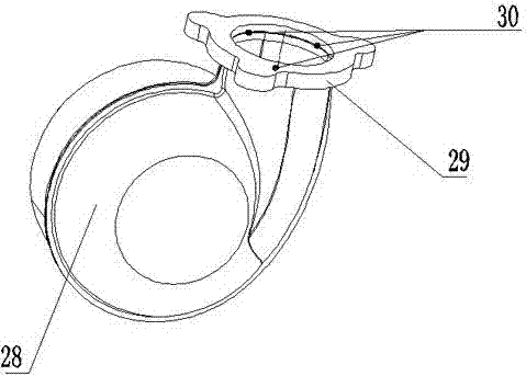
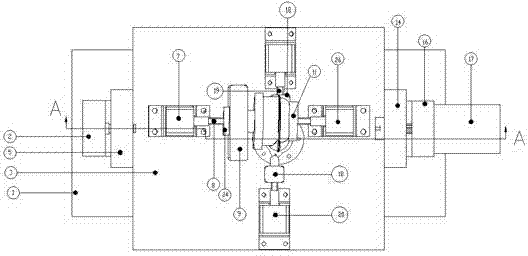
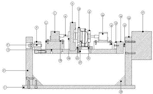
[0010] See figure 2 and image 3 , the present invention comprises a base plate 3, a support frame, a rotary cylinder 17 and a workpiece positioning clamping device, wherein the support frame comprises a support plate 1, and support blocks 2, 16 are installed at both ends of the support plate 1, and the support plate 1 and the support block 2, 16 are strengthened and connected by reinforcing ribs 22, and the rotary cylinder 17 is fixed on the lateral right end support block 16 of the support frame, and the two ends of the bottom plate 3 are installed on the support blocks 2, 16 through the coupling blocks 5, 14, and the coupling blocks 14 is connected and fixed with the output transmission shaft 15 of the rotary cylinder 17, the coupling block 5 is installed on the support block 2 through the support shaft 4, the flange positioning boss 23 is fixed on the bottom plate 3, and the flange positioning boss 23 is provided with a flange The inner hole with matching shape, the bott...


PUM


Abstract

The invention provides a flange spot welding clamp for an automobile exhaust recirculation cooling system diffuser. The clamp can ensure the positioning precision of a flange and a diffuser shell during spot welding. The clamp comprises a bottom plate. The clamp is characterized by also comprising a support frame, a rotary cylinder and workpiece positioning and clamping devices; the support frame comprises a support plate, and a support block is arranged at each of two transverse ends of the support frame; the rotary cylinder is fixed on the support block at the transverse right end of the support frame; two transverse ends of the bottom plate are arranged on the support blocks through connecting blocks, and the connecting block at the right end is connected and fixed with an output transmission shaft of the rotary cylinder; and a flange positioning boss is fixed on the bottom plate, the flange positioning boss is provided with an inner hole matched with the shape of the flange, the bottom plate is provided with a conical through hole at the position opposite to the flange positioning boss, and one workpiece positioning and clamping device is arranged on each of the transverse side and the longitudinal side of the flange positioning boss on the bottom plate.

Description

technical field [0001] The invention relates to the technical field of parts processing of an automobile exhaust gas recirculation system, in particular to the technical field of parts processing of an automobile exhaust gas recirculation system. Background technique [0002] A diffuser of an automobile exhaust gas recirculation cooling system, the structure of which is shown in figure 1 After the diffuser shell 28 and the flange 29 are connected by TIG welding, in order to ensure the size and welding fastness of the diffuser shell 28 and the flange 29 TIG welding, the diffuser shell is welded by spot welding before welding. 28 and the preliminary fixation of the inner hole wall of the flange 29, figure 1 Middle 30 is the spot welding position of the flange, and then TIG welding of the overall connection side is performed. Since the diffuser has high installation accuracy requirements, it must ensure that the plane on the flange reaches the circular cavity axis of the diffu...

Claims


Application Information

Patent Timeline
Patent Type & Authority Applications(China)
IPC IPC(8): B23K37/047
Inventor 白瑛
Owner WUXI DAWN DIE & STAMPING
Why Eureka
Try Eureka