

Boring and milling head
A technology for boring and milling and boring shafts, applied in the field of boring and milling heads, can solve the problems of increased equipment transmission chain, increased equipment complexity, inconvenient speed control and other problems, and achieves the effect of convenient control and reasonable structure
- Summary
- Abstract
- Description
- Claims
- Application Information
AI Technical Summary
Problems solved by technology
Method used
Image

Examples
Embodiment Construction
[0009] The present invention is further described below in conjunction with embodiment and accompanying drawing.
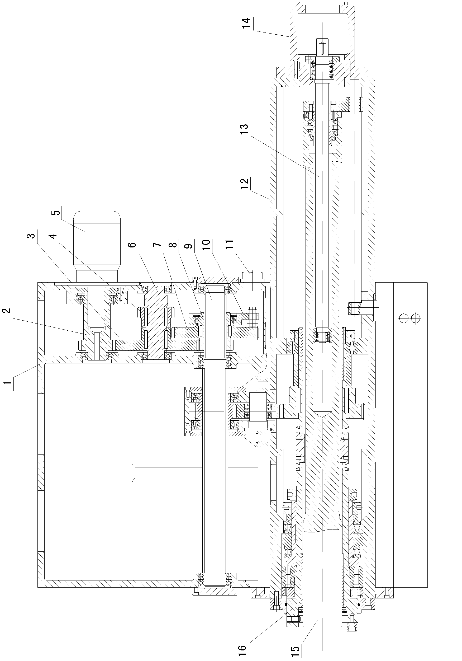
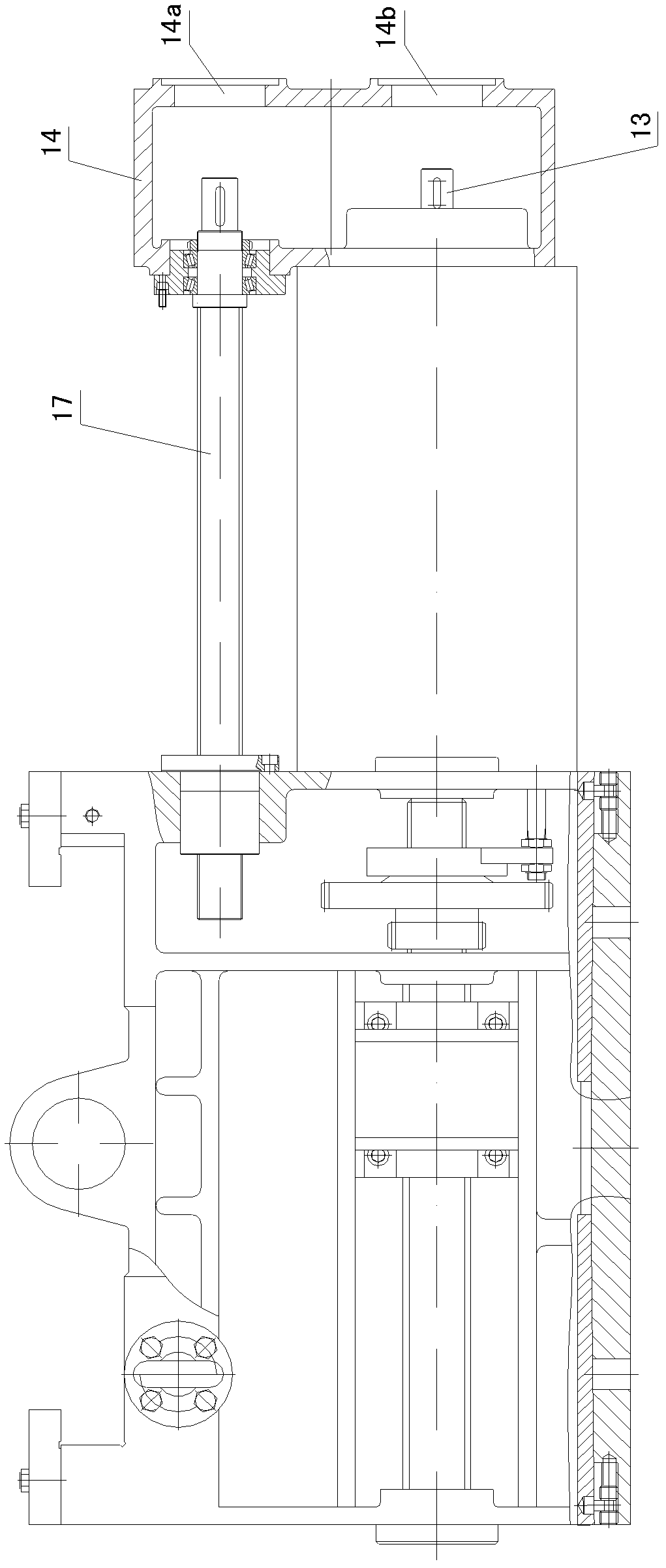
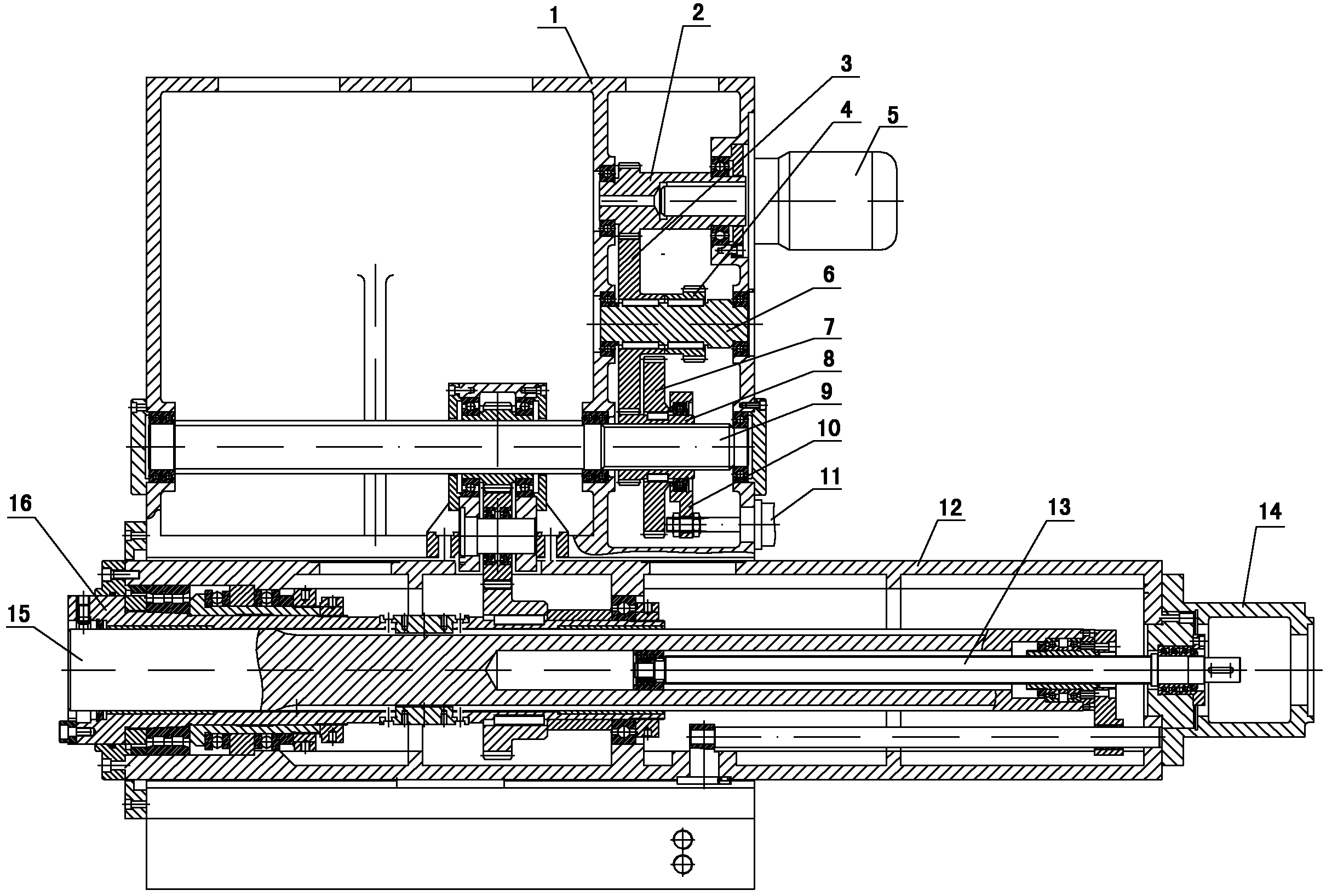
[0010] see figure 1 , figure 2
[0011] The basic structure of the boring and milling head provided by the present invention is the same as that of the prior art. A square ram 12 is installed in the box body 1. A square ram feeding mechanism is installed between the square ram 12 and the box body. The boring shaft 15 is mounted on a square ram. Inside the ram 12, the milling shaft 16 is installed on the boring shaft 15, the boring shaft feeding mechanism is installed between the boring shaft 15 and the square ram 12, the driving gear shaft 2, the intermediate shaft 6, and the transmission spline are installed in the box body 1 Shaft 9, driving gear shaft 2 is connected with main motor 5, transmission spline shaft 9 and milling shaft 16 are connected with transmission mechanism, intermediate shaft 6 is equipped with large gear 3 and pinion 4, and large gear 3 me...
PUM
 Abstract
Description
Claims
Application Information