Supercharge Your Innovation With Domain-Expert AI Agents!

Clamping mechanism of clamp of machine tool

A technology of clamping mechanism and machine tool fixture, applied in the direction of clamping, manufacturing tools, metal processing mechanical parts, etc., can solve the problems of large volume, fixture installation or use restrictions, etc., to achieve the effect of reduced volume and compact structure

Inactive Publication Date: 2012-07-11
SHANGHAI UNIV OF ENG SCI
View PDF3 Cites 4 Cited by
  • Summary
  • Abstract
  • Description
  • Claims
  • Application Information

AI Technical Summary

Problems solved by technology

This kind of mechanism has a large volume, and the oil (air) cylinder is a swing design, so the installation or use of the fixture is often limited due to the insufficient swing space of the oil cylinder.

Method used


Image

  • Clamping mechanism of clamp of machine tool
  • Clamping mechanism of clamp of machine tool
  • Clamping mechanism of clamp of machine tool

Examples


Embodiment Construction

[0012] The present invention will be described in detail below in conjunction with the accompanying drawings and specific embodiments.

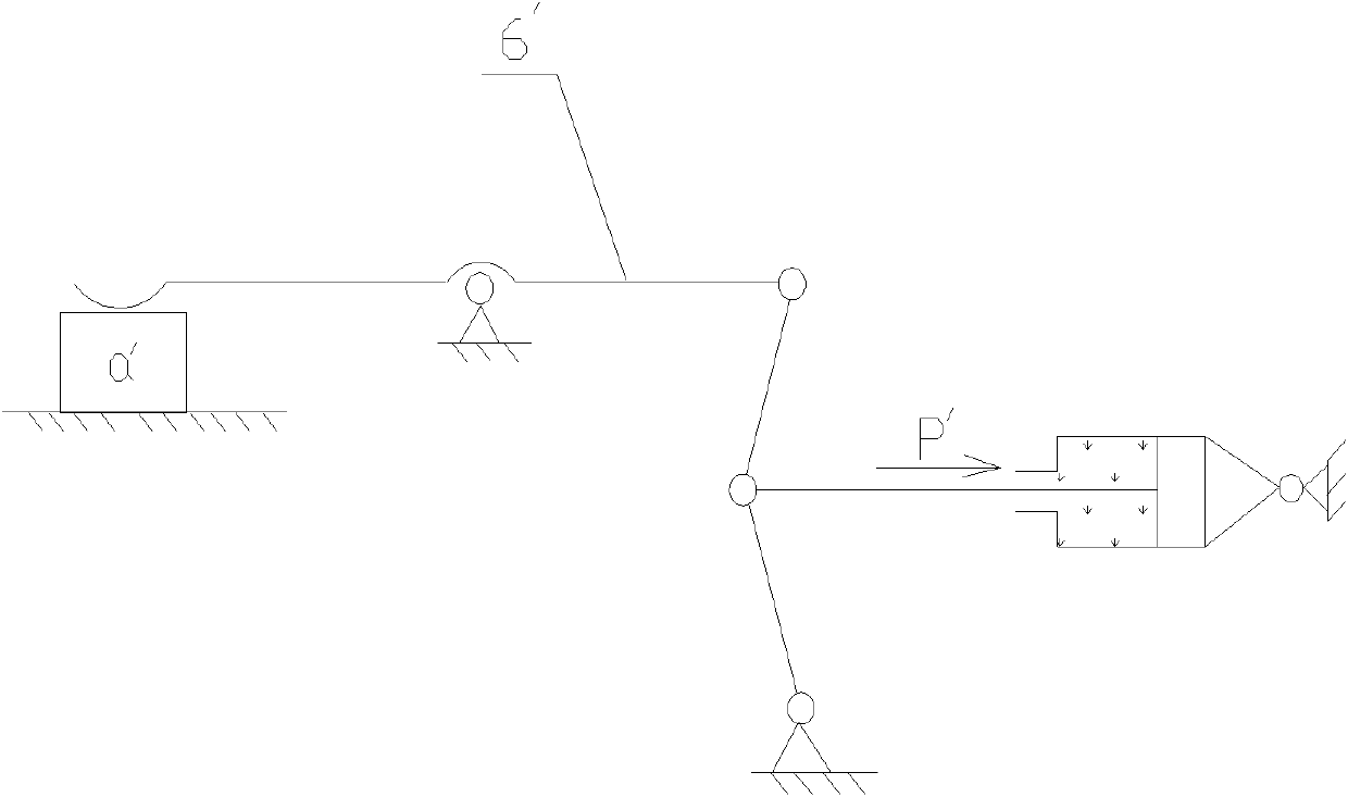
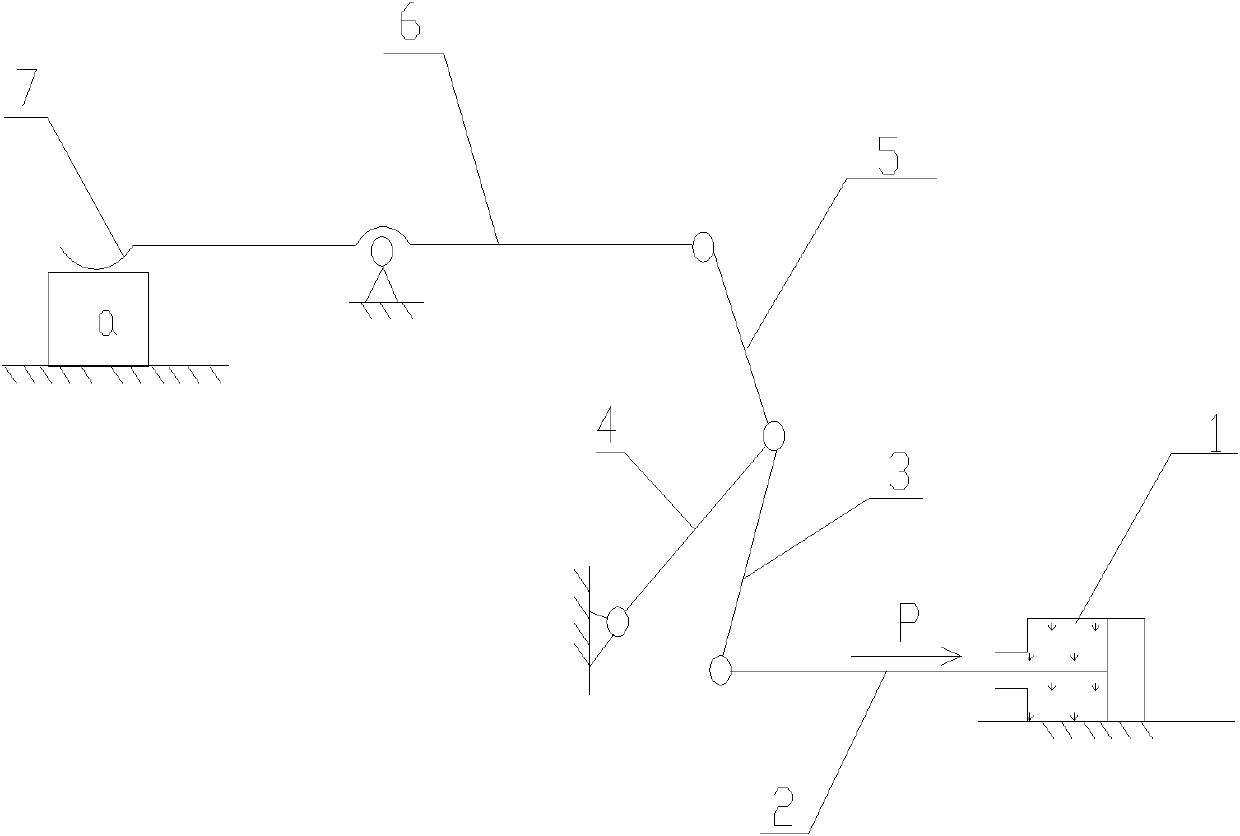
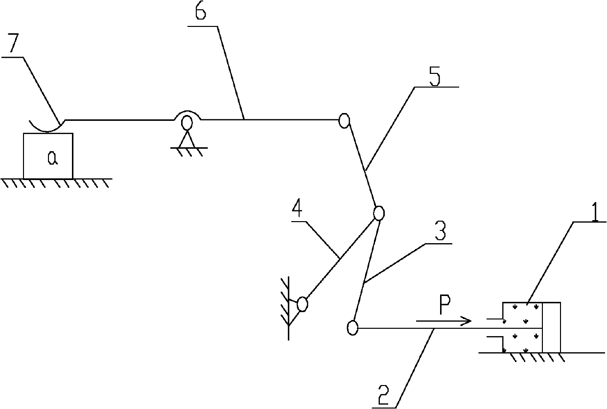
[0013] Such as figure 2 As shown, a clamping mechanism of a machine tool fixture is used to clamp a workpiece a. The mechanism includes a driving device 1, a transmission rod 2, a push rod 3, a rotating rod 4, a push rod 5, and an actuator rod 6. The driving device 1 is fixedly arranged In the mechanism, one end of the transmission rod 2 is in transmission connection with the driving device 1, and the other end is movably connected with the ejector rod 3. One end of the rotating rod 4 is movably connected with the mechanism, and the other end is movably connected with the ejector rod 3 and the push rod 5. One end is movably connected with the actuator rod 6, the middle part of the actuator rod 6 is movably connected with the mechanism through a fulcrum, and the front end of the actuator rod 6 is provided with a clamping element 7 for clampin...


PUM


Abstract

The invention relates to a clamping mechanism of a clamp of a machine tool. The clamping mechanism is used for clamping a workpiece and comprises a driving device, a transmission rod, an ejection rod, a rotating rod, a push rod and an execution rod, wherein the driving device is fixedly arranged in the mechanism; one end of the transmission rod is in transmission connection with the driving device, and the other end of the transmission rod is movably connected with the ejection rod; one end of the rotating rod is movably connected with the mechanism, and the other end of the rotating rod is movably connected with the ejection rod and the push rod; the other end of the push rod is movably connected with the execution rod; the middle part of the execution rod is movably connected with the mechanism through a supporting point; and the front end of the execution rod is provided with a clamping element for clamping the workpiece. Compared with the prior art, the layout mode of the driving device of the conventional six-link hinge clamping mechanism is changed; a swing cylinder is changed into a fixed cylinder; the number of hinges used on the mechanism is not increased; and therefore, the size of the clamp is reduced, the structure is more compact, and the limitation in mounting or use brought by insufficient swing space of the driving device can be made up.

Description

technical field [0001] The invention relates to a clamping mechanism, in particular to a clamping mechanism of a machine tool fixture. Background technique [0002] When machining workpieces on metal cutting machine tools, fixtures must be used to install the workpieces in order to position and clamp the workpieces. Positioning is to make the workpiece have a correct position relative to the tool on the machine tool. Clamping is to fix the workpiece after positioning, so that it can maintain the correct position determined during positioning during processing, so that qualified parts that meet the requirements can be processed. Component. Therefore, the clamp has two main components: the positioning element and the clamping device, and the clamping device can generally be divided into two parts: the power device and the clamping mechanism. The power device is the power source that generates the clamping force. The power source can come from pneumatic, hydraulic and electri...

Claims


Application Information

Patent Timeline
Patent Type & Authority Applications(China)
IPC IPC(8): B23Q3/00
Inventor 华健
Owner SHANGHAI UNIV OF ENG SCI
Features
  • R&D
  • Intellectual Property
  • Life Sciences
  • Materials
  • Tech Scout
  • Unparalleled Data Quality
  • Higher Quality Content
  • 60% Fewer Hallucinations
Learn More