

Two-plate type mould locking device
A clamping device, two-plate technology, applied in the field of two-plate clamping device, can solve the problems of complex control, low reliability, and many parts, and achieve the effect of simple control, high reliability, and few parts
- Summary
- Abstract
- Description
- Claims
- Application Information
AI Technical Summary
Problems solved by technology
Method used
Image

Examples
Embodiment 1
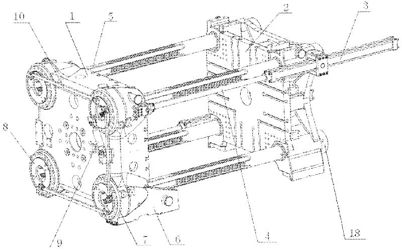
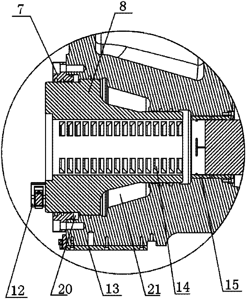
[0032] Such as Figure 1 to Figure 12 As shown, a two-plate mold clamping device includes a movable platen 1, a fixed platen 2, a mold shifting cylinder 3, a piston rod 4, a tie rod 5, a sliding foot 6, a piston back cover 7, a clamping piston 8, and a brake cylinder 9. Connecting connecting rod 10, connecting rod connecting seat 12, slider 13, ring tooth 14, guide sleeve 15, pull rod nut 18, mold breaking cavity 20 and mold locking cavity 21, the four corners of the fixed template 2 plane The tie rod 5 is fixed by the tie rod nut 18, the movable template 1 is installed on the tie rod 5, the mold transfer cylinder 3 is installed on the diagonal line of both sides of the fixed template 2, and the output end of the mold transfer cylinder 3 is connected to the corresponding side of the movable template 1, The four corners of the movable template 1 are piston back covers 7, and the mold locking piston 8 is installed in the piston back cover 7, and a transmission system is installe...
Embodiment 2
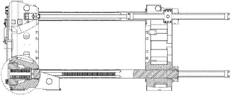
[0049] Such as Figure 7 ~ Figure 8 As shown, when the mold is closed, the mold shifting cylinder 3 pulls the movable template 1, and moves to the right along the pull rod 5 to close the mold. The connecting rod 10 drives the other mold locking piston 8 to rotate, so that the ring teeth 14 of the mold locking piston 8 and the ring teeth on the tie rod 5 change from the separated state to the meshing state, and the mold locking cavity 21 is oiled to push the mold locking The piston 8 moves toward the piston back cover 7, and forms the clamping force.
[0050] When the mold is opened, the clamping chamber 21 releases the mold clamping force, and the mold breaking chamber 20 enters the oil to push the mold clamping piston 8 into the piston back cover 7, and forms the mold breaking force to break the mold, and the output shafts of the two brake cylinders 9 move separately , to drive the mold clamping piston 8 to rotate, and at the same time, the connecting rod 10 drives the other...
Embodiment 3
[0053] Such as Figure 9 ~ Figure 10As shown, when the mold is closed, the mold shifting cylinder 3 pulls the movable template 1, and moves to the right along the pull rod 5 to close the mold. The connecting rod 10 drives the respective mold locking pistons 8 to rotate, so that the ring teeth 14 of the mold locking piston 8 and the ring teeth on the tie rod 5 change from the separated state to the meshing state, and the mold locking chamber 21 pushes the mold locking piston 8 with oil. Move toward the piston back cover 7 and form the clamping force.
[0054] When the mold is opened, the clamping cavity 21 releases the clamping force, and the mold breaking cavity 20 enters the oil to push the clamping piston 8 into the piston back cover 7, and forms a mold breaking force to break the mold, and the output shafts of the two brake cylinders 9 move, Drive the mold-locking piston 8 to rotate, and at the same time, the three connecting rods 10 drive the respective mold-locking pisto...
PUM
 Abstract
Description
Claims
Application Information