Flying-wing layout aircraft provided with cycloidal propellers

A cycloid propeller and aircraft technology, applied in the field of aeronautical aircraft, can solve the problem of not giving full play to the unique advantages of the cycloid propeller, and achieve the effects of improving the range and load, high aerodynamic efficiency, and improving the lift-to-drag ratio.

Inactive Publication Date: 2012-07-11
NORTHWESTERN POLYTECHNICAL UNIV
View PDF9 Cites 10 Cited by
  • Summary
  • Abstract
  • Description
  • Claims
  • Application Information

AI Technical Summary

Problems solved by technology

It has not been considered comprehensively with the aircraft itself, and

Method used


Image

  • Flying-wing layout aircraft provided with cycloidal propellers
  • Flying-wing layout aircraft provided with cycloidal propellers
  • Flying-wing layout aircraft provided with cycloidal propellers

Examples


Embodiment Construction

[0044] Describe the present invention below in conjunction with specific embodiment:

[0045] This embodiment is a flying-wing layout aircraft with a cycloidal propeller, which includes a flying-wing layout body, a cycloidal propeller propeller and two elevons 6 .

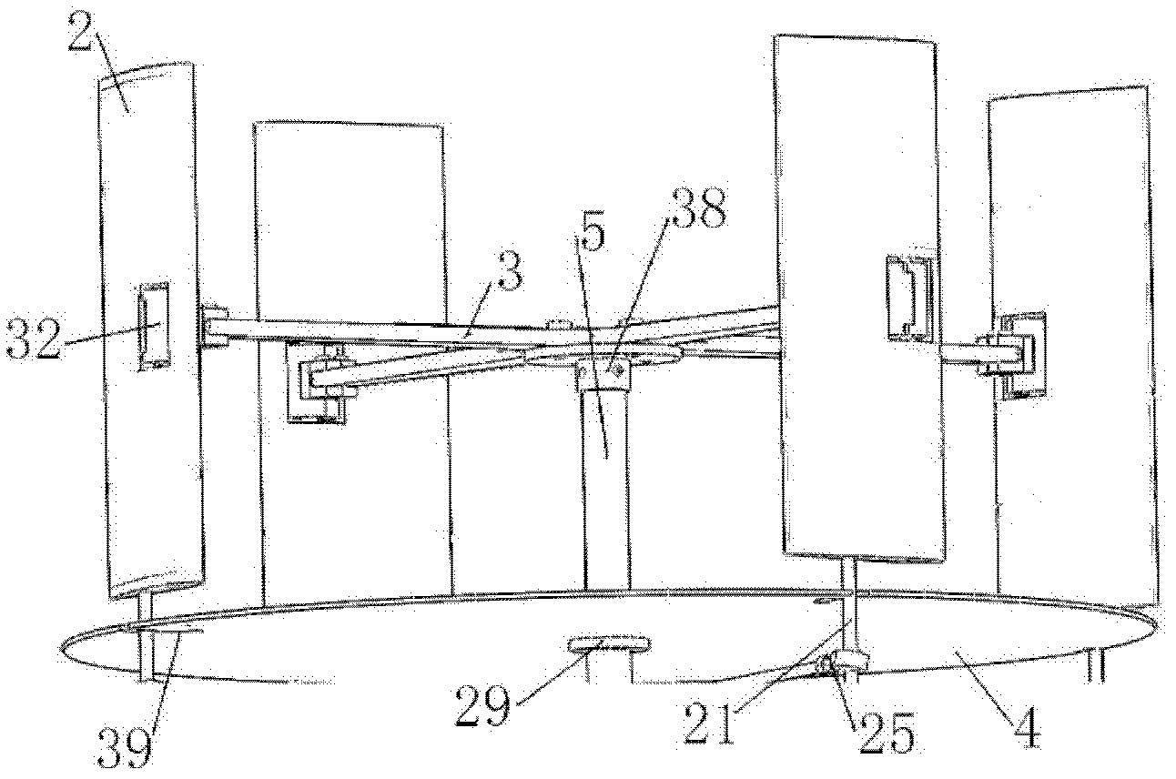
[0046] Refer to attached Figure 13 And attached Figure 14 , the flying wing layout body comprises flying wing skin 1, fuselage rib 9, wing tip rib 10, flying wing fuselage section front beam 11, flying wing fuselage section middle beam 12, flying wing fuselage section rear beam 13, Flying wing front beam 14, flying wing rear beam 15 and other structures; two elevons are respectively installed on the outer side of the rear edge of the flying wing layout body. is 30mm. The pilot issues instructions to make the left and right elevons 6 deflect upwards or downwards at the same time, so that the pitch control of the aircraft can be realized; if the left and right elevons 6 deflect one upward and the other downward,...


PUM


Abstract

The invention provides a flying-wing layout aircraft provided with cycloidal propellers. The flying-wing layout aircraft comprises a flying-wing layout aircraft body, a cycloidal propeller thruster and two elevons; wherein the cycloidal propeller thruster is symmetrically arranged above the flying-wing layout aircraft body along the symmetrical surfaces of the flying-wing layout aircraft body, and the paddles of the cycloidal propeller thruster are arranged on the outer side of the upper surface of the flying-wing layout aircraft body; a driving device of the cycloidal propeller thruster is located in the flying-wing layout aircraft body; the cycloidal propeller thruster comprises cycloidal propeller blades, a paddle bracket, a cycloidal propeller rotating shaft, the driving device and an eccentric circular ring locating mechanism; and the eccentric circular ring locating mechanism comprises a control pill rod, an eccentric rotary circular ring, an eccentric hollow cylinder locating platform and an auxiliary locating pull rod. In the invention, the cycloidal propeller has higher aerodynamic efficiency than that of a screw propeller so that fuels can be saved and the voyage and the load of the aircraft can be improved; two cycloidal propellers have all-around vectored thrusts and can directly control the flight direction; and air on the upper surface of the flying wing can flow faster through airflow produced by the cycloidal propellers so that the lift-to-drag ratio of the flying wing can be improved.

Description

technical field [0001] The invention belongs to the technical field of aviation aircraft, in particular to an aircraft with a flying wing layout equipped with cycloidal propellers. Background technique [0002] The fuselage of a traditional conventional aircraft basically does not generate lift, and the lift is basically provided by the wings. The body of most of the area of ​​the aircraft with flying wing layout can generate lift, so under the same thrust condition, the flying wing layout can allow greater load capacity. Under the condition of given range and load, the thrust required by the flying wing layout is small, the fuel consumption is low, and the cost is reduced. Flying wings have shown great advantages in terms of weight, manufacturing cost, aerodynamic performance and appearance. Therefore, designing high-performance flying-wing aircraft has always been the relentless pursuit of many aircraft designers. [0003] US Patent No. 7,753,309B2 applied by Garreau et...

Claims


Application Information

Patent Timeline
IPC IPC(8): B64C3/38B64D35/00
Inventor 胡峪唐继伟宋笔锋
Owner NORTHWESTERN POLYTECHNICAL UNIV
Why Eureka
Try Eureka