Method for producing asphalt blending oil by normal pressure distillation of catalytic slurry oil
A technology of catalyzing oil slurry and atmospheric distillation, which is applied in the multi-stage series refining process, etc., can solve the problems of low utilization efficiency of oil slurry, coking of equipment nozzles, affecting the normal use of equipment, etc., and achieves wide parameter adjustment range, The effect of reducing operating costs and equipment investment
Inactive Publication Date: 2012-07-11
甘黎明 +2
View PDF10 Cites 31 Cited by
- Summary
- Abstract
- Description
- Claims
- Application Information
AI Technical Summary
Problems solved by technology
[0003] At present, most of the catalytic cracking oil slurry is used as the blending oil of fuel oil. The utilization efficiency of the oil slurry is
Method used
View moreImage
Smart ImageViewing Examples
Examples
 PUM
| Property | Measurement | Unit |
|---|---|---|
| Flash point | aaaaa | aaaaa |
| Flash point | aaaaa | aaaaa |
| Flash point | aaaaa | aaaaa |
Abstract
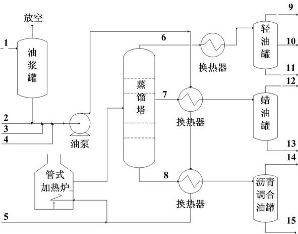
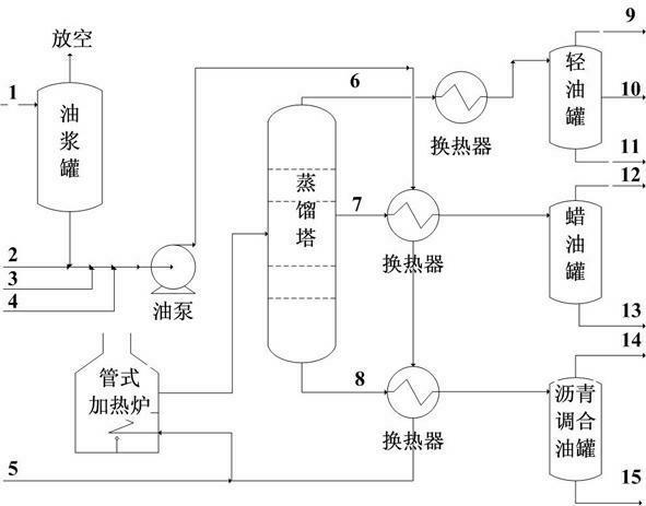
The invention relates to a method for producing asphalt blending oil by normal pressure distillation of catalytic slurry oil. The method comprises the steps of: adding a certain amount of additives, such as a steam partial pressure regulator and an oxidant and the like, into catalytic cracking slurry oil as a raw material, pumping the material into a heat exchanger by an oil pump for preheating; after the material is preheated, conveying the material into a heating furnace for heating to be 360-420 DEG C, and conveying the material into a distillation tower for separating; obtaining a mixture of top light oil and the steam partial pressure regulator at the top of the tower, and if the steam partial pressure regulator is not soluble in the light oil, standing and separating to obtain the light oil; distilling off wax oil from a middle outlet of the tower; obtaining high boiling point heavy oil, as the asphalt blending oil, containing small amounts of catalyst microparticles at the bottom of the tower; and if high boiling point heavy oil not containing powders is needed, removing residual microparticles by a high temperature filter to obtain cleaner high boiling point heavy oil.
Description
technical field [0001] The invention relates to a method for continuously producing bitumen blended oil by using the externally thrown oil slurry of a catalytic cracking production device as a raw material, adding an auxiliary agent for atmospheric distillation, and belonging to the heavy oil treatment technology of petrochemical industry. Background technique [0002] The oil slurry produced in the catalytic cracking process of heavy oil accounts for about 5-10% of the processing capacity of the catalytic cracking unit. Catalytic cracking slurry has high density, small hydrogen to carbon atom ratio, high residual carbon value, high aromatic hydrocarbon content, and short side chain fused ring aromatic hydrocarbons account for more than 70% of the total aromatic hydrocarbons. The catalytic oil slurry contains a small amount of catalyst micro-particles, the content of which is generally about 500-1000 ug / g, and the diameter of the micro-particles is about 5 μm. In operation,...
Claims
Login to View More Application Information
Patent Timeline
 IPC IPC(8): C10G53/02
Inventor 甘黎明陈天晓曲蓉
Owner 甘黎明
Features
- R&D
- Intellectual Property
- Life Sciences
- Materials
- Tech Scout
- Unparalleled Data Quality
- Higher Quality Content
- 60% Fewer Hallucinations
Learn More Browse by: Latest US Patents, China's latest patents, Technical Efficacy Thesaurus, Application Domain, Technology Topic, Popular Technical Reports.
© 2025 PatSnap. All rights reserved.Legal|Privacy policy|Modern Slavery Act Transparency Statement|Sitemap|About US| Contact US: help@patsnap.com


