Eureka AIR delivers breakthrough ideas for toughest innovation challenges, trusted by R&D personnel around the world.

Supplying thermal energy to a working element and/or cover element of a flat card or roller card

A technology for working elements and carding elements, used in deburring devices, fiber processing, textiles and papermaking, etc., to achieve the effect of eliminating temperature gradients

Active Publication Date: 2012-07-11
特吕茨施勒集团欧洲公司
View PDF6 Cites 4 Cited by
  • Summary
  • Abstract
  • Description
  • Claims
  • Application Information

AI Technical Summary

Problems solved by technology

The disadvantage is that when the machine is cold, a concave curvature is created which is preset to be the same for all working conditions

Method used


Image

  • Supplying thermal energy to a working element and/or cover element of a flat card or roller card
  • Supplying thermal energy to a working element and/or cover element of a flat card or roller card
  • Supplying thermal energy to a working element and/or cover element of a flat card or roller card

Examples


Embodiment Construction

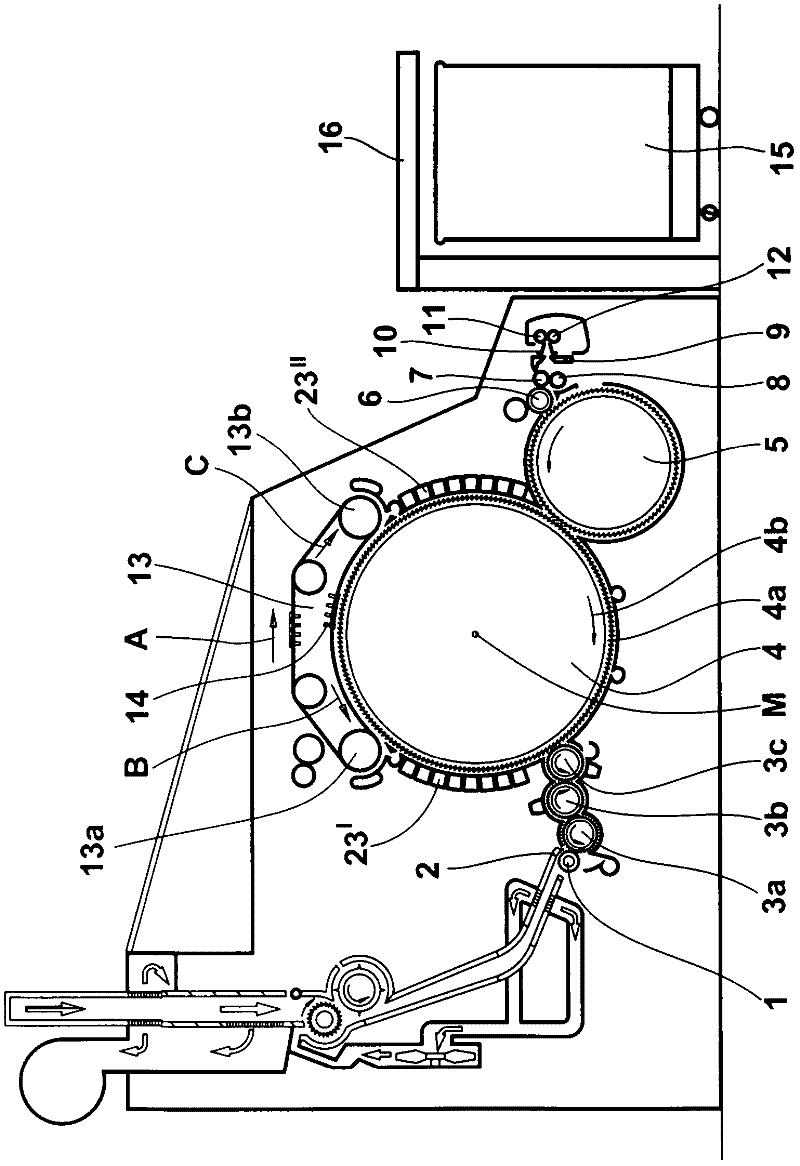
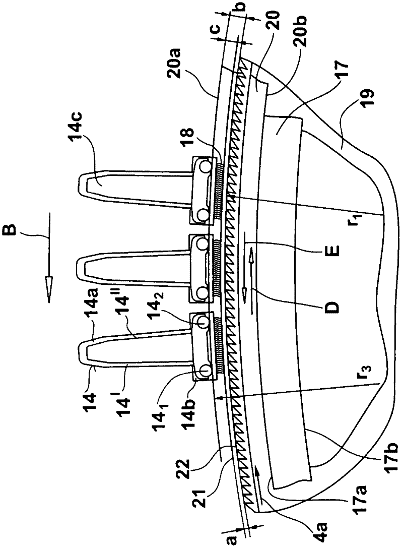
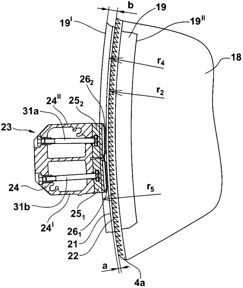
[0019] figure 1 Shows a card, for example a flat card TC 07 from Trützschler, with feed roller 1, feed disc 2, licker-in rollers 3a, 3b, 3c, cylinder 4, doffer 5, stripping roller 6, nipper Outlet rollers 7, 8, web guide 9, web funnel 10, delivery rollers 11, 12, revolving cover top 13 with cover guide rollers 13a, 13b, cover T-shaped iron bar 14, can 15 and coiling machine 16. The direction of rotation of the rollers is indicated by the curved arrows. Reference sign M denotes the center point (axis) of the cylinder 4 . The reference numeral 4a designates the card clothing and the reference numeral 4b designates the deflection of the cylinder 4 . The reference sign B indicates the turning direction of the revolving flat top 13 in the carding position, the reference sign C indicates the return conveying direction of the flat T-shaped iron bar 14, wherein the reference signs 30', 30" indicate functional elements, and the reference sign 13a and 13b represent the cover guide r...


PUM


Abstract

Apparatus on a flat card or roller card comprises at least one working element 14 and / or cover element arranged opposite and spaced apart from a clothed roll 4 and extending over the width of the roll. The element has an elongate carrier member comprising a foot and a back, the foot facing towards the roll absorbs operating heat and the back facing away from the roll is in contact with ambient air. To allow adjustment of the working element and / or cover element to different fibre materials and operating circumstances or conditions and to enable the carding nip to be constant, thermal energy is supplied to the back preferably to provide a largely homogeneous temperature distribution having a very small or no temperature gradient in the carrier member. The working element may comprise a fixed card or a revolving flat assembly. In the case of a revolving flat assembly the thermal energy may be supplied by a heating zone which makes brushing contact with the backs of several flats and is preferably confined to the flat entry region. The heating zone may comprise one or more blankets 27 with which a temperature profile may be established over the working width to counteract different temperature gradients

Description

technical field [0001] The invention relates to a device on a flat or roller card, in which there is at least one working and / or covering element which is arranged opposite a card clothing roller and is connected to The clothing roller is spaced apart, the at least one working and / or covering element extends over the entire working width of the clothing roller and has an elongated carrier member comprising a base and a back, wherein the clothing facing The base of the roll absorbs the operating heat, while the back of the roll facing away from the clothing is in contact with the surrounding air. Background technique [0002] In modern high-performance cards, the heating of the components and the associated spacing changes between the components play an increasingly important role. The same is true for the spacing between the cylinder and the flat bar of the cover plate. In order to be able to achieve high quality at maximum production speed, the distance must remain as con...

Claims


Application Information

Patent Timeline
IPC IPC(8): D01G15/26D01G15/28D01G15/12D01G15/14
CPCD01G15/24D01G15/26
Inventor C·莱因德斯
Owner 特吕茨施勒集团欧洲公司
Why Eureka
Eureka Blog
Learn More