Carding machine carrier element with tensioning element

A technology of working elements, functional elements, applied to flat carding machines or roller cards with at least one working and/or functional element, such as stationary carding elements, revolving flats in the field of equipment

Active Publication Date: 2012-07-11
TRUETZSCHLER GRP SE
View PDF7 Cites 4 Cited by
  • Summary
  • Abstract
  • Description
  • Claims
  • Application Information

AI Technical Summary

Problems solved by technology

Its disadvantage is that when the machine is cold, it produces a concave curve which is preset to be the same for all operating states

Method used


Image

  • Carding machine carrier element with tensioning element
  • Carding machine carrier element with tensioning element
  • Carding machine carrier element with tensioning element

Examples


Embodiment Construction

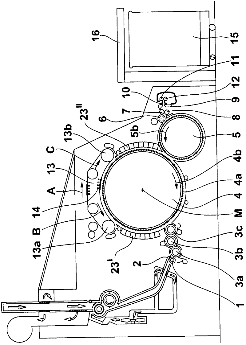
[0034] refer to figure 1 , a carding machine, such as the flat carding machine TC of Trutzshler GmbH & Co.Kg of Monchengladbach, Germany, has a feeding roller 1, a cotton feeding disc 2, licker-in rollers 3a, 3b, 3c, cylinder 4 , doffer 5, stripping roller 6, nip roller 7, 8, web guide 9, web funnel 10, delivery roller 11, 12, revolving flat top 13 with flat guide roller 13a, 13b and cover Lath 14 , can 15 and coiled strip 16 . Reference sign M denotes the center point (axis) of the cylinder 4 . Reference numeral 4a indicates the card clothing, and reference numeral 4b indicates the deflection of the cylinder 4. Arrow A indicates the working direction. The curved arrow shown inside the roller indicates the turning of the roller.

[0035] In the pre-carding zone (between the licker-in roller 3c and the rear flat guide roller 13a), a plurality of stationary carding elements 23' according to the invention are arranged opposite the cylinder 4, in the rear carding zone (the fro...


PUM


Abstract

A flat or roller card comprises is at least one working element and / or functional element, for example a fixed carding element or revolving flat bar with an elongate carrier element 24. A tensioning element 51 associated with the carrier element allows adjustment of the working element to enable the carding nip to be constant. A clamping device 50 is provided with which the position of the tensioning element 51 is fixable with respect to the carrier element 24. The clamping device may be used to pre-tension the working element such that an operational temperature differential causes the working element to bow in a complimentary manner to the associated working cylinder. Alternatively the clamping element may be activated in use by an increasing temperature differential. Preferably a steel rod 51 is located inside an aluminium tube 52 which is in-turn located within a recess of the carrier element with insulation between the tube and carrier element. The clamping device preferably comprises a sleeve nut threaded onto the aluminium tube and has claws with chamfered surfaces such that screwing the nut onto the tube or relative thermal expansion of the tube and carrier element causes the claws to clamp onto the rod 51.

Description

technical field [0001] The invention relates to a device on a flat card or a roller card, in which there is at least one working and / or functional element, such as a stationary carding element, a revolving flat strip. The working and / or functional elements of the carding machine usually have an elongated carrier element between the two end regions for supporting on the carding machine, this element has an area directed towards the inside (in the working area of ​​the carding machine), which is connected to the The cylinder card clothings are arranged oppositely and spaced apart from each other. Background technique [0002] In cards designed today, the carding elements used for the carding process are flats with flexible clothings (revolving flats) and / or stationary carding elements with all-steel clothings, the actual clothings being covered by high-precision carrier parts Keep. It is customary now to use extruded aluminum profiles as load-bearing parts. Such profiles ha...

Claims


Application Information

Patent Timeline
Patent Type & Authority Applications(China)
IPC IPC(8): D01G15/28
CPCD01G15/26D01G15/24
Inventor B·雅各布斯
Owner TRUETZSCHLER GRP SE
Why Eureka
Try Eureka