Door lock mechanism

A door lock and driving mechanism technology, which is applied to building locks, other washing machines, building structures, etc., can solve the problems of not producing DC motors, not being able to accommodate the door lock mechanism, and jamming, and achieve cost reduction, reliable operation, and easy operation. The effect of manufacture

Inactive Publication Date: 2012-07-11
ILLINOIS TOOL WORKS INC
View PDF5 Cites 5 Cited by
  • Summary
  • Abstract
  • Description
  • Claims
  • Application Information

AI Technical Summary

Problems solved by technology

[0005] First, door lock manufacturers generally do not produce DC motors, which need to be outsourced, and the cost and cycle are not easy to control
[0006] Second, a DC power supply and / or an AC-to-DC circuit is required
[0007] Third, when the driving structure of the screw (crew) device is in use, because the starting torque of the ordinary DC motor is relatively small and sensitive to voltage, it will sometimes get stuck and cause the failure of the washing machine cover to be opened.
[0008] Fourth, the door lock mechanism is relatively large, and the door equipment of some electrical equipment (including the upper cover of the washing machine) cannot accommodate such a door lock mechanism.

Method used


Image

  • Door lock mechanism
  • Door lock mechanism
  • Door lock mechanism

Examples


Embodiment Construction

[0048] In the following drawings, the same reference numerals are used for the same components, and the similar reference numerals are used for similar components to avoid repeated descriptions.

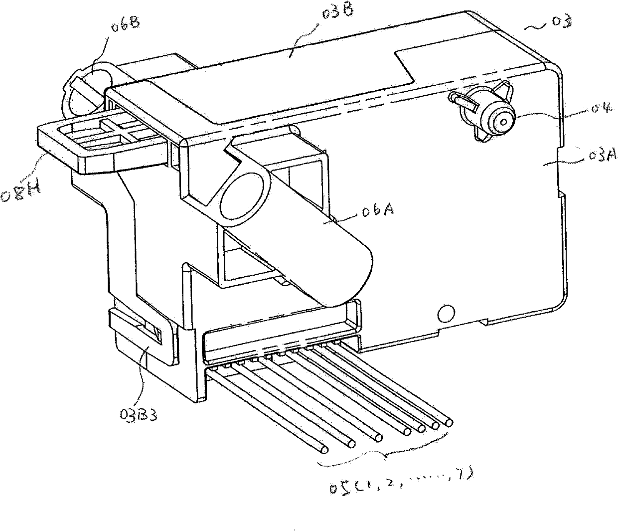
[0049] figure 1 It is an overall external view of the door lock mechanism 002 of the present invention. Such as figure 1 As shown, there is a door lock mechanism housing 003 outside the door lock mechanism 002, including a front housing cover plate 003A and a rear housing cover plate 003B. There is a shaft hole cap 004 on the upper right part of the front housing cover plate 003A, which is used to cover a shaft hole 003C (not shown) on the front housing cover plate 003A, and the shaft hole is used for installing the rocker shaft 22 (see Figure 5 ) of one end 22A, the rocker shaft 22 (see Figure 5) is installed in a shaft hole 003D (not shown) on the front housing cover plate 003B. There is a group of cables 005 (005.1, 005.2, ..., 005.7) at the lower left part of the front hous...


PUM


Abstract

The invention discloses a door lock mechanism of electrical equipment. The door lock mechanism can prevent the release caused by manual misoperation or vibration. The door lock mechanism comprises a locking arm, a locking dog, a coil iron core, a first coil and a second coil, wherein the locking arm swings around a shaft; the locking dog is connected with the locking arm; when the locking arm swings around the shaft, the locking dog moves to a locking position or a release position; the coil iron core is connected with the locking arm, and the linear reciprocating motion of the coil iron core pushes the locking arm to swing around the installing shaft of the locking arm; and the first coil and the second coil are used for driving the coil iron core to move back and forth and driving the locking arm to swing, thereby leading the locking dog to be in the locking position or release position. An alternating current voltage is directly used for the door locking mechanism, thereby an alternating current to direct current circuit is omitted; and the coil iron core directly pushes the locking arm, thereby a screw device is omitted. The door lock mechanism provided by the invention has simple structure and reliable operation and is easy to manufacture.

Description

technical field [0001] The invention relates to a door lock mechanism of electrical equipment, in particular to a door lock mechanism of electrical equipment capable of preventing release caused by human misoperation or vibration. Background technique [0002] The use safety of electrical equipment has certain requirements on the door lock mechanism of the equipment. Taking a large-scale top loading washing machine as an example, the locking of its top plate has certain requirements on the door lock mechanism. One of the requirements is that if the top cover of the washing machine can be opened when the large drum type washing machine is running, because the washing machine is rotating at a high speed (or still rotating at a high speed due to inertia), it may cause harm to the human body. Therefore, when the washing machine door lock mechanism is running in the washing machine, even if someone operates the door opening device of the washing machine at this time or the washi...

Claims


Application Information

Patent Timeline
IPC IPC(8): D06F37/28D06F37/42E05B47/02E05B65/00
Inventor 汪洋
Owner ILLINOIS TOOL WORKS INC
Why Eureka
Try Eureka