
Hollow slab bridge and construction method thereof

A hollow slab bridge and hollow slab technology, applied in bridge construction, bridges, buildings, etc., can solve problems such as difficult construction, stress on veneer, and difficulty in ensuring quality, simplify prefabrication and construction technology, and enhance shear force. The effect of the transmission capacity and the force transmission path of the mortise and tenon is clear

Inactive Publication Date: 2012-07-11
ZHENGZHOU UNIV
View PDF2 Cites 19 Cited by
  • Summary
  • Abstract
  • Description
  • Claims
  • Application Information

AI Technical Summary

Problems solved by technology

[0003] Since adjacent hollow slabs are only connected and transmitted by grooved steel bars and concrete, the slab-to-slab connection capacity is insufficient, and the integrity of the bridge is poor.
Moreover, the size of the grooved joint is generally relatively small, the construction is difficult, and the quality is not easy to be guaranteed, resulting in low strength and easy damage of the grooved joint, resulting in shear damage of the grooved joint, and even the formation of a single plate under force, increasing the deflection of the hollow plate, Cracks appear on the bridge deck along the longitudinal direction of the bridge at the position of the tongue and groove, destroying the pavement layer of the bridge deck, causing bumpy driving, thus affecting the normal use and durability of the bridge, and burying hidden dangers to the safety of bridge traffic

Method used


Image

  • Hollow slab bridge and construction method thereof
  • Hollow slab bridge and construction method thereof
  • Hollow slab bridge and construction method thereof

Examples


Embodiment

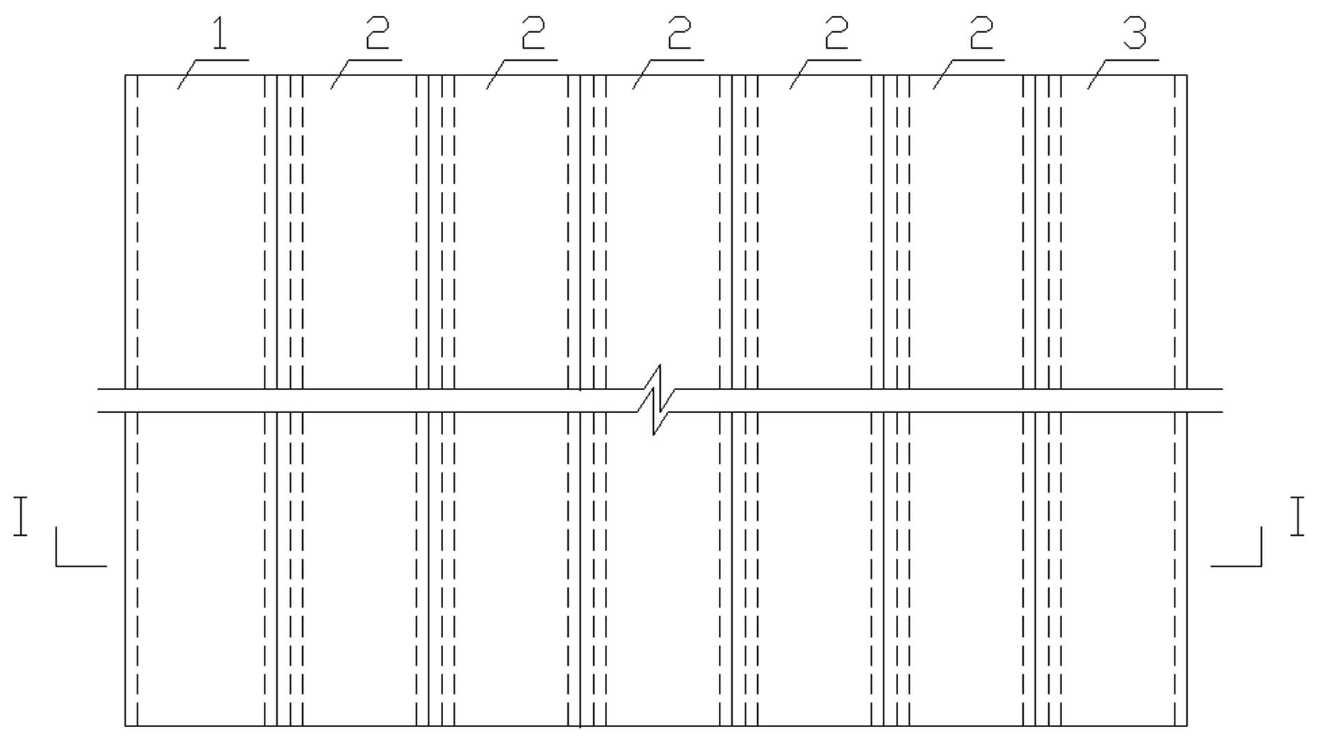
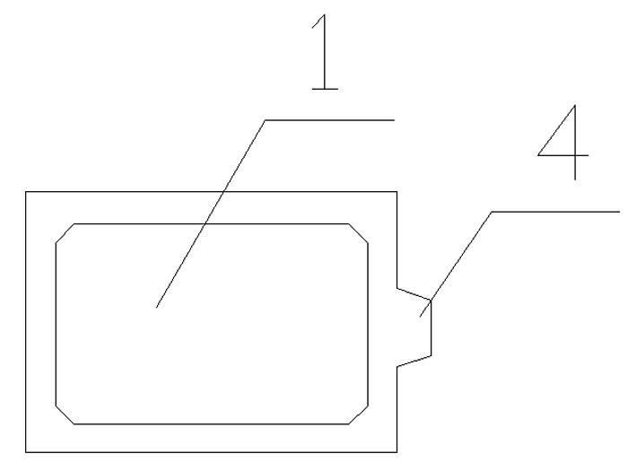
[0024] Example: such as Figure 1-5 As shown, a hollow slab bridge comprises edge hollow plates 1, 3 on both sides and a hollow core plate 2 laid continuously in the middle. The middle part of one side of the hollow core plate 2 is provided with a recessed groove to form a groove 5, and the other side The middle part is provided with a protruding convex strip 4; the lower surface of the groove 5 is an upwardly inclined slope or a plane, the upper surface of the groove 5 is a downwardly inclined slope or a plane, and the lower surface of the matching convex strip 4 is An upwardly inclined slope or plane, the upper surface of the raised strip 4 is a downwardly inclined slope or plane; one side of the outer side hollow plate is a straight edge, and the other side is provided with a groove 5 matching the adjacent hollow plate or rib 4. Steel bars are arranged in the groove 5 and the protruding strip 4, and the ends of the protruding strip 4 and the groove 5 are provided with cham...


PUM


Abstract

The invention discloses a hollow slab bridge, which comprises side hollow slabs on two sides and middle hollow slabs continuously laid in the middle, wherein the middle part of one side of each middle hollow slab is provided with a sunken groove, and the middle part of the other side of each middle hollow slab is provided with a raised strip; the lower surface of the groove is an upwards inclined bevel or plane, the upper surface of the groove is a downwards inclined bevel or plane, the lower surface of the raised strip matched with the groove is an upwards inclined bevel or plane, and the upper surface of the raised strip is a downwards inclined bevel or plane; and one side of each side hollow slab close to the edge is a straight edge, and the other side of each side hollow slab is provided with a groove or a raised strip matched with the adjacent middle hollow slab. A construction method for the hollow slab bridge comprises the following steps of: prefabricating the hollow slabs; hoisting the hollow slabs; and treating the grooves and the raised strips. Tongue and groove joints are not required in the hollow slab bridge, and the transverse shearing force is not transferred through concrete among the tongue and groove joints, so that the transverse integrity of the hollow slab bridge is improved, and the shearing force transfer capacity among the slabs is enhanced.

Description

technical field [0001] The invention relates to a hollow slab bridge and a construction method thereof. Background technique [0002] Prefabricated hollow slab bridges are widely used in highway construction due to their reliable quality and convenient and fast construction, especially in small and medium-sized highway bridges with a span of less than 20m. The construction method of this type of bridge is to hoist the prefabricated hollow slabs in place, then pour concrete at the position of the grooved joint between adjacent hollow slabs, pave the bridge deck, pass the steel bars and concrete of the grooved joint and pave the bridge deck. Connect each hollow plate horizontally along the bridge to form a whole. The hollow slab of this type of bridge is constructed in a prefabrication plant, and the cross-section is usually in the form of a single-hole or double-hole section. The pre-tensioning method is used to arrange prestressed steel bars along the longitudinal direction...

Claims


Application Information

Patent Timeline
IPC IPC(8): E01D2/00E01D21/00
Inventor 陈淮葛素娟王艳陈栋高冰李杰李静斌李胜利
Owner ZHENGZHOU UNIV
Learn More